


2
33Chapter 2 Installation
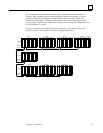
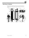
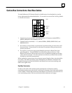
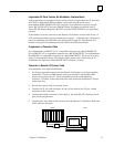
Genius Bus Connections: Dual Bus Cables
To install a Remote I/O Scanner directly on both busses of a redundant bus, use the
lower eight terminals as described below. Do not attach an external Bus Switching Module
to a Remote I/O Scanner.
TERMINALS
FOR
BUS A
TERMINALS
FOR
BUS B
5 6
3
1
7
9
11
4
2
8
10
12
R
E
D
U
N
D
A
N
C
Y
SER1
SER1A
SER2A
SER1B
SER2B
a44881
SHIELD
OUT B
SHIELD
IN B
SHIELD
OUT A
SHIELD
IN A
SHIELD
IN
SHIELD
OUT
SER2
1. Connect bus A to terminals 5 – 8 on the Remote I/O Scanner, marked SER1A,
SER2A, SHIELD IN A and SHIELD OUT A.
2. Connect bus B to terminals 9 – 12, marked SER2A, SER2B, SHIELD IN B, and
SHIELD OUT B.
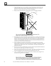
3. For each bus, connect Serial 1 to the Serial 1 terminals of the previous device and
the next device. Connect Serial 2 to the Serial 2 terminals of the previous device
and the next device.
4. For each bus, connect the appropriate Shield In terminal to Shield Out of the
preceding device. Connect Shield Out to Shield In of the next device. If the
Remote I/O Scanner is the first device on a bus, its Shield In terminal for that bus
can be left unconnected. If it is the last device on the bus, its Shield Out terminal
for that bus can be left unconnected.
When making bus connections, the maximum exposed length of bare wires should be
two inches. For added protection, each shield drain wire should be insulated with
spaghetti tubing to prevent the Shield In and Shield Out wires from touching each
other or the signal wires.
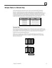
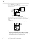
Dual Bus Termination
If either trunk cable of the dual bus ends at the Remote I/O Scanner, install a
terminating resistor across the Serial 1 and Serial 2 terminals where that cable attaches
to the module. If both cables terminate at the Remote I/O Scanner, each must have its
own terminating resistor. Do not terminate dual bus stubs (see next page).