


2
Series 90–70 Remote I/O Scanner User’s Manual – July 199234
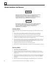
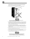
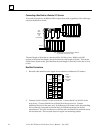
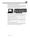
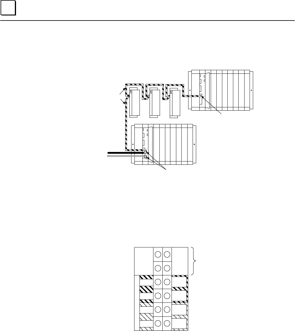
Connecting a Bus Stub to a Remote I/O Scanner
A bus stub must always be Belden 9182 or equivalent cable, regardless of the cable type
used for the dual bus trunk.
BUS A
a44882
BUS B
BUS
STUB
BELDEN
9182
OR
EQUIVALENT
NO TERMINATING RESISTOR
TERMINATING RESISTOR NEEDED IF REMOTE
I/O SCANNER IS AT END OF A BUS.
The total length of all stubs on a bus should be 100 feet or less. Within each 20%
section of the actual bus length, the total maximum stub length is 20 feet. This can be
divided into shorter stubs, provided that the total length in each 20% of the bus is 20 ft.
or less.
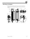
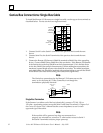
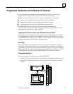
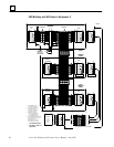
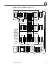
Bus Stub Connections
1. Bus stub cable attaches to the upper four terminals on a Remote I/O Scanner.
CONNECT
BUS
STUB CABLE
HERE
5 6
3
1
7
9
11
4
2
8
10
12
R
E
D
U
N
D
A
N
C
Y
SER1
SER1A
SER2A
SER1B
SER2B
a44883
SHIELD
OUT B
SHIELD
IN B
SHIELD
OUT A
SHIELD
IN A
SHIELD
IN
SHIELD
OUT
SER2
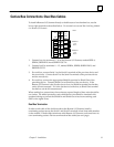
2. Connect Serial 1 to Serial 1 of the next device. Connect Serial 2 to Serial 2 of the
next device. Connect Shield Out to Shield In of the next device. Connect
additional devices in the same way. If the Remote I/O Scanner is the bus switching
device (directly connected to the dual bus), its Shield In terminal can be left
unconnected. If it is the last device on the bus stub, the Shield Out terminal can be
left unconnected. The bus stub does not require a terminating resistor.