


2
Series 90–70 Remote I/O Scanner User’s Manual – July 199236
Logicmaster 90 Serial Version and Workstation Interface Board
If the programmer is equipped with the serial version of Logicmaster 90–70 and a
Workstation Interface Board (IC647WMI920 for Workmaster II or IBM PS/2 computer,
or IC640WMI910 for a Workmaster or IBM PC–XT/AT computer), connection is made
to the Remote I/O Scanner’s RS–485 serial port. If the Remote I/O Scanner is not part
of a multidrop network, follow the instructions below. If the Remote I/O Scanner is
installed on a multidrop serial communications network, refer to the instructions on
page 39 instead.
The Workstation Interface Board can be used for either parallel or serial
communications with a remote drop. The board provides ground isolation allowing
the programmer ground to vary by up to 500V.
Grounding
For proper operation, the programmer must have a ground connection in common
with rack 0. Normally, the common ground connection is provided by connecting the
programmer’s power cord to the same power source (with the same ground reference
point) as the rack. If a common ground cannot be established, use GE Fanuc RS–422
Isolated Repeater/RS–232 Converter IC655CCM590, or an equivalent product.
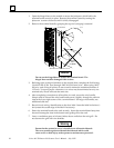
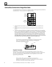
Serial Port Termination
For direct programmer connection, the Remote I/O Scanner’s serial port must be
terminated. Connect a 220Ω resistor across pins 10 and 11 and another 220Ω resistor
across pins 8 and 15. These connections must be made inside the connector’s D–shell.
At the other end of the link, terminate the RD and CTS pins in the same way.
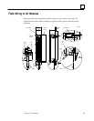
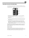
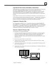
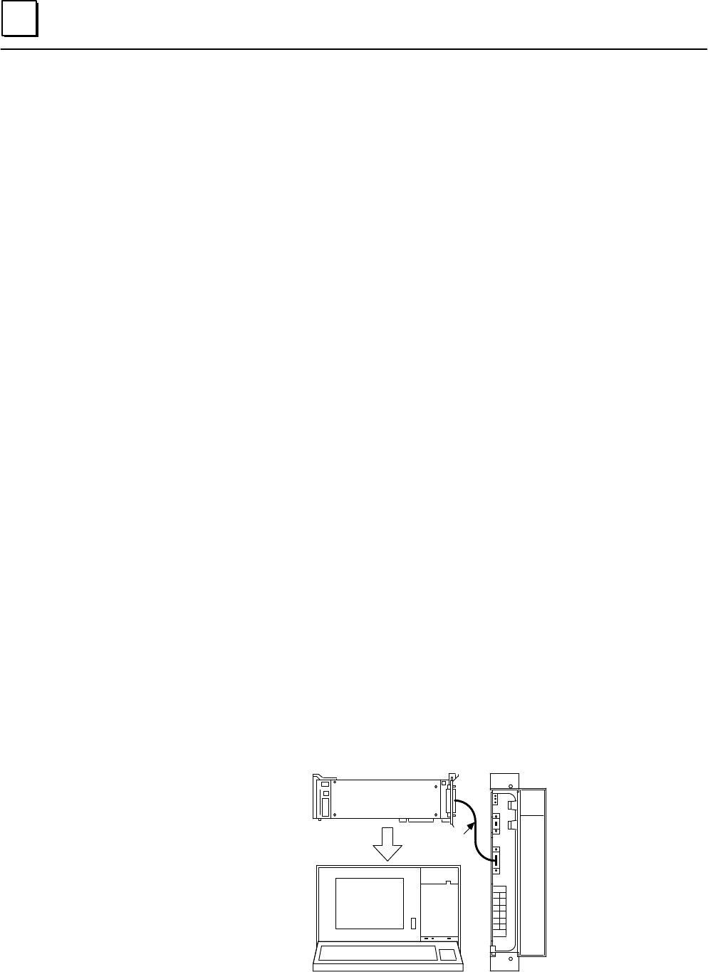
Connection Instructions
For a Workmaster I or II computer, use cable IC647CBL704.
1. Attach the 37–pin male connector to the Workstation Interface Board.
2. Attach the 15–pin male connector to the serial port connector on the Remote I/O
Scanner.
WSI
SERIAL
WORKMASTER
a44884
SERIAL
CABLE
SCANNER
WORKMASTER II