


2
Series 90–70 Remote I/O Scanner User’s Manual – July 199238
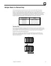
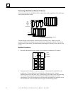
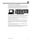
Multidrop Connections
Multidrop connections are described in the Series 90–70 Installation and Operation
Manual (GFK–0262). Additional instructions are given below. Connection is made
between the CPU and the serial port on the Remote I/O Scanner.
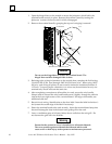
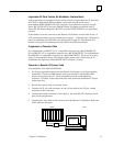
Terminating the Remote I/O Scanner’s Serial Port
The serial port on the Remote I/O Scanner must be terminated if the Remote I/O
Scanner will be at the end of a multidrop network. To terminate the serial port, connect
a 220Ω resistor across pins 10 and 11 and another 220Ω resistor across pins 8 and 15.
These connections must be made inside the connector’s D–shell. At the other end of
the link, terminate the RD and CTS pins in the same way.
Note
SNP termination is the same for Series 90–70 CPUs IC697CPU731K or
later, and IC697CPU771H or later. For Series 90–70 CPUs
IC697CPU771J or earlier and IC697CPU771G or earlier, the jumper is
located between pins 9 and 10.
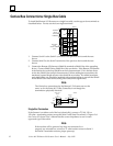
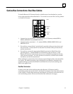
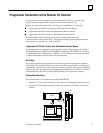
Isolation for the Serial Port
Like the Series 90–70 CPU, the Remote I/O Scanner contains NO isolation circuitry at
the SNP port. If isolation is required, use the GE Fanuc RS–232/RS–422 converter
(catalog number IC655CCM590), or equivalent product.
Caution
If a multidrop network cannot be guaranteed to be on the same
electrical ground and served by the same phase on the mains,
isolation must be provided separately for each CPU and Remote I/O
Scanner.