


6
6-18 Genius Modular Redundancy Flexible Triple Modular Redundant (TMR) System
User’s Manual – March 1995
GFK-0787B
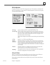
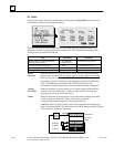
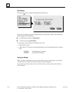
I/O Limits
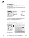
Select System again. From the configuration menu, select Config Limits (click the mouse
on that line or cursor down and press Enter).
Entries made on this screen determine how the GMR software allocates memory. The
maximum number of groups that can be configured is 128. Additional parameter limits
for this screen are summarized below.
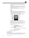
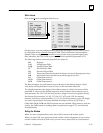
Item Parameters Comment
Total number of voted digital inputs
and redundant outputs
1...112 (788 CPU)
1...2048 (789 CPU)
In increments of 16 or 32
Number of voted analog inputs 1...1024 In increments of 4 or 6
%AI Analog Input Table size 1...8192
%R register table size 1 to 16 Specified in increments of 1K
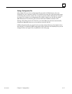
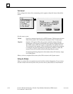
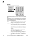
Enter the number of 16-circuit and 32-circuit discrete input and output
groups in the system (plus any spare groups you may add in the future).
Each input group may consist of 1, 2, or 3 blocks. The GMR software will
assign these voted I/O addresses at the beginning of the I/O tables, and
“raw” data addresses at the end of the I/O tables (similar to the
illustration of analog inputs, below, and discussed in detail in chapter 7).
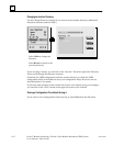
Enter the number of groups made up of 6-input analog blocks and the
number of groups made up of 4-input (2-output) blocks. Include any
spare groups you may add in the future
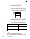
Enter the amounts of word memory to be allocated to analog input data
(%AI) and register data (%R). These values must match the
corresponding values configured using Logicmaster 90.
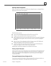
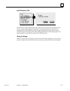
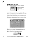
%AI Size: Allow enough %AI memory to accommodate all analog input
data, as explained below. The maximum size is 8192 analog channels (words).
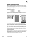
%AI memory is divided into sections:
Voted Inputs
non-voted
Inputs
Input
Voting
Logic
A inputs
A
B
C
B inputs
C inputs
%AI0001
Voted
Discrete
Analog
In Groups
Tables