


6
6-47GFK-0787B Chapter 6 Configuration
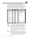
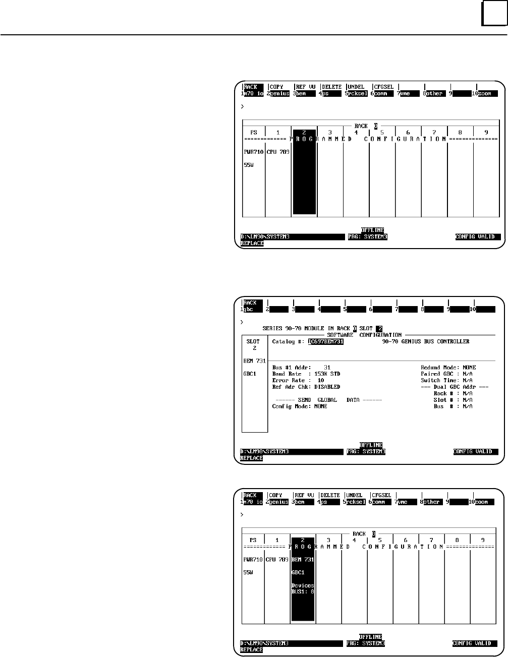
Logicmaster Configuration Summary
1. Change the CPU to the correct type (in
this example, it is a CPU 789) and add
appropriate memory.
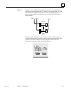
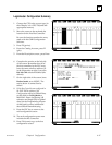
2. Move the cursor to the rack and slot
location for the first Bus Controller.
Be sure the location matches the entry
made with the GMR Configuration
Software.
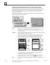
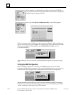
3. Press F2 (genius).
4. From the Catalog # screen, press F1
(gbc).
5. From the Description screen, press Enter.
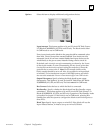
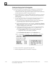
6. Complete the entries on the left side
of the screen. Remember that all of
the bus controllers in the PLC must
have the same serial bus address (31
in the illustration at right). Leave the
Ref Adr Chk selection disabled (the
default).
7. On the right side of the screen, leave
Redund mode set to NONE. The
entries below it cannot then be
edited.
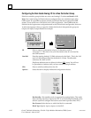
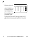
8. If this Bus Controller was configured in
the INIT DATA window of the
Configuration utility, for Global Data,
set the field for Config Mode to
MANUAL. Enter a beginning %R
reference and length (64) for global
data. See the Programming chapter
of this book for more information
about Global Data addressing.
9. Press the ESC key to return to the
rack configuration screen.
10. The rack configuration screen now
includes the Bus Controller.
11. Press F10 (zoom) to go to the bus
configuration screen.