


6
6-51GFK-0787B Chapter 6 Configuration
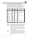
Configuring 16-Circuit and 32-Circuit Discrete DC Blocks
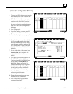
The table below lists configuration parameters for 16-circuit and 32-circuit discrete
blocks. Configuration options with special requirements in GMR systems are described
after the table. Configuration options that are not changed for GMR systems are not
described here. Note that blocks do not prevent selecting incorrect parameters for a
GMR system. It is important to configure blocks appropriately for GMR use.
Feature Circuit or
Block
Factory
Setting
Selections
Device Number Block null 0 to 31 (a number must be selected)
Reference Address Block none Depends on host CPU type
Block I/O Type Block input input, output, combination
Baud Rate Block 153.6 std 153.6 std, 153.6 ext, 76.8, 38.4 Kbd
Pulse Test for Outputs Block enabled enabled, disabled
Input Filter Time
(16–ckt)
(32 ckt)
Block 20mSec
5–100mSec
1–100mSec
Circuit I/O Type Circuit input input, output, tristate input*
Report Faults Circuit yes yes, no
Hold Last State Circuit no yes, no
Output Default State Circuit off on, off
Detect No Load* Circuit yes yes, no
Overload Shutdown* Circuit yes yes, no
BSM Present Block no yes, no
BSM Controller Block no yes, no
Output Default Time Block 3 bus scans (for bus redundancy) 2.5 or 10 sec
Redundancy Mode Block none none, hot standby, duplex, GMR
Duplex Default Block off on, off
* Available only with 16–circuit blocks.
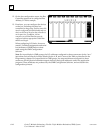
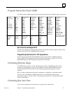
In a triple-redundancy GMR system, serial bus addresses 29 – 31 are
reserved for the bus controllers. By convention, serial bus address 0 is
often used for the Genius Hand-held Monitor. The serial bus addresses
assigned to the blocks must match those entered using the GMR
Configuration Software. Therefore 1–28 are available for blocks.
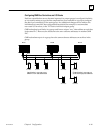
All the blocks in an input group must be configured to use the same
serial bus address. In a 4-block output group, three of the blocks (one
each on bus A, B, and C) use the same serial bus address. The fourth
block, which must be located on either bus A or bus B, must be assigned
a different serial bus address.
All blocks in the same output group must use the same reference
address. However, blocks in an input group each have a unique address,
as explained on page 6-37. Refer to the reference address assignments
made using the GMR Configuration Software when assigning addresses
to blocks. Reference addresses must be assigned on 8-bit boundaries.
The system may include individual blocks that are not set up for
redundancy.
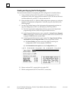
Device
Number
(serial bus
address)
Reference
Address