


8
8-3GFK-0787B Chapter 8 Installation Information
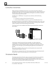
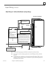
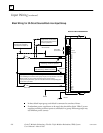
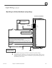
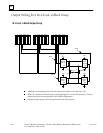
Input Wiring
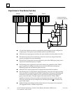
Calculating Voltage Drops on Tristate Inputs
It is important to consider the field wiring runs required for devices configured as
tristate inputs. Devices that are powered by 24V DC will have a voltage-reducing
component inserted at the field device to provide an input threshold range for three
states. The table on page 2-7 shows appropriate ranges. Wiring runs can reduce the
voltage at the input block terminal further, to an inoperable level, depending on the
length, conductor, and gauge. Isolation diodes placed before the terminal on the input
will also drop the voltage.
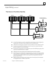
Most applications do not have limitations created by these factors. However, to ensure
that all input state operations are indicated correctly, calculations should include the field
signal voltage, the wire resistance times the length and the voltage drop in any barriers
or isolation devices, to determine the actual voltage present at the input terminal.
Additional information about input blocks is located in the Genius I/O Discrete and Analog
Blocks User’s Manual (GEK-90486-2).