


8
8-5GFK-0787B Chapter 8 Installation Information
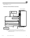
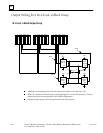
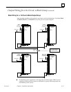
Input Wiring (continued)
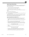
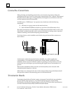
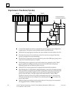
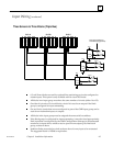
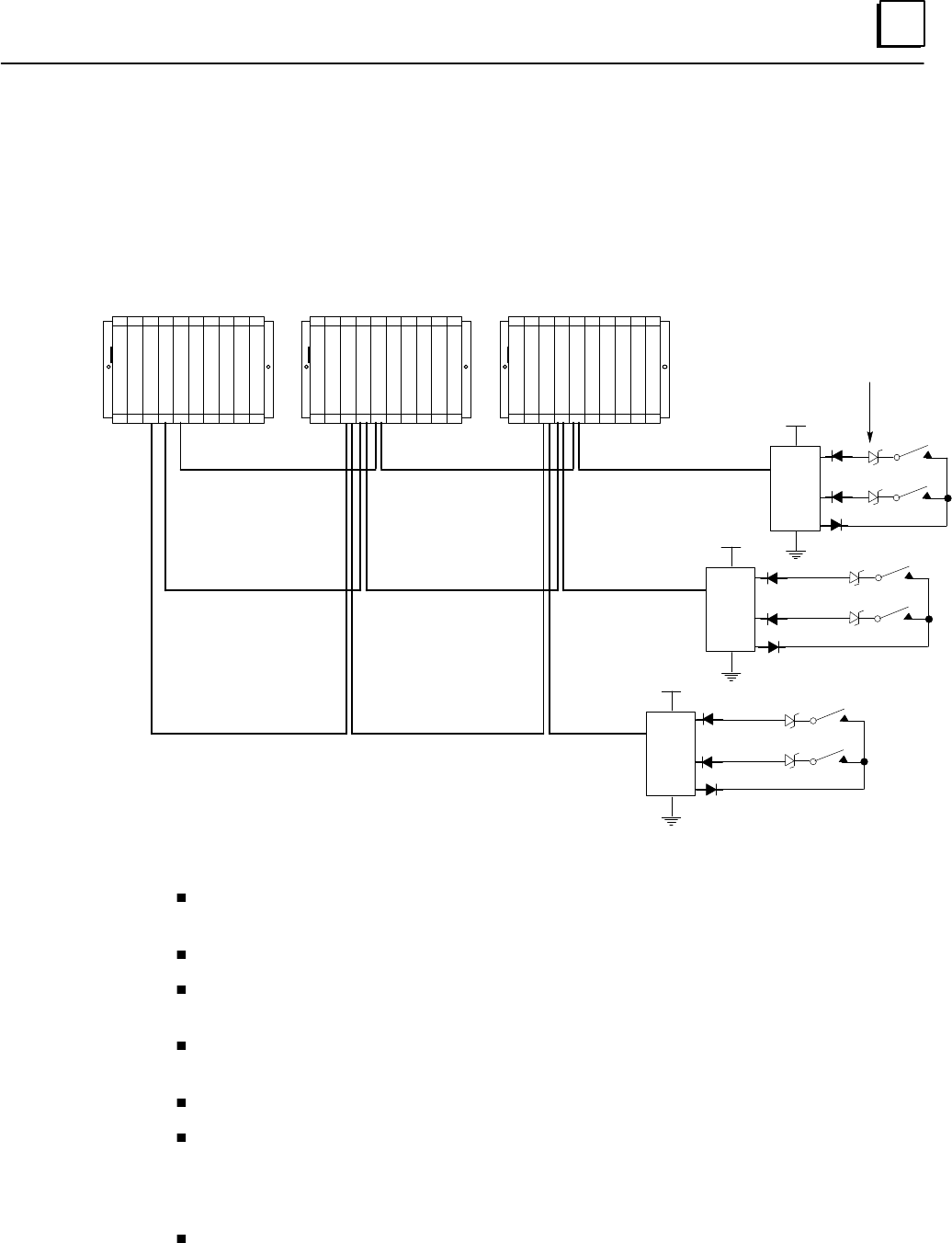
Three Sensors to Three Blocks (Triple Bus)
DC+
I1
I15/32
O16
I1
I15/32
O16
I1
I15/32
O16
Input 1
Input 15 or 32
Input 1
Input 15 or 32
Input 1
Input 15 or 32
DC+
DC+
PLC A PLC B PLC C
6.2V Zener Diodes for
Line Monitoring (optional)
C
P
U
G
B
C
C
G
B
C
A
G
B
C
B
C
P
U
G
B
C
A
G
B
C
B
G
B
C
C
C
P
U
G
B
C
A
G
B
C
B
G
B
C
C
P
S
P
S
P
S
6.2 volt Zener diodes are used for optional line monitoring on circuits configured as
tristate inputs. This option is only available with 16-circuit DC blocks.
All blocks in an input group must have the same number of circuits (either 16 or 32).
On either 16-circuit or 32-circuit blocks, circuit 16 is used as an output if the block
group is configured for input autotesting.
On any block, circuits that are not configured as part of the GMR input group can be
used as non-redundant inputs or outputs.
All blocks in the input group must be assigned the same serial bus address.
If the block group is configured for input autotesting, it must be wired appropriately.
Each input that is configured (by the GMR Configuration Software) to be autotested
must have its input device wired to receive power from output Q16 of the block
group, as shown above.
Isolation diodes must also be wired as shown above for any input to be autotested.
The suggested diode is 1N5400 or equivalent.