


8
8-9GFK-0787B Chapter 8 Installation Information
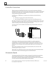
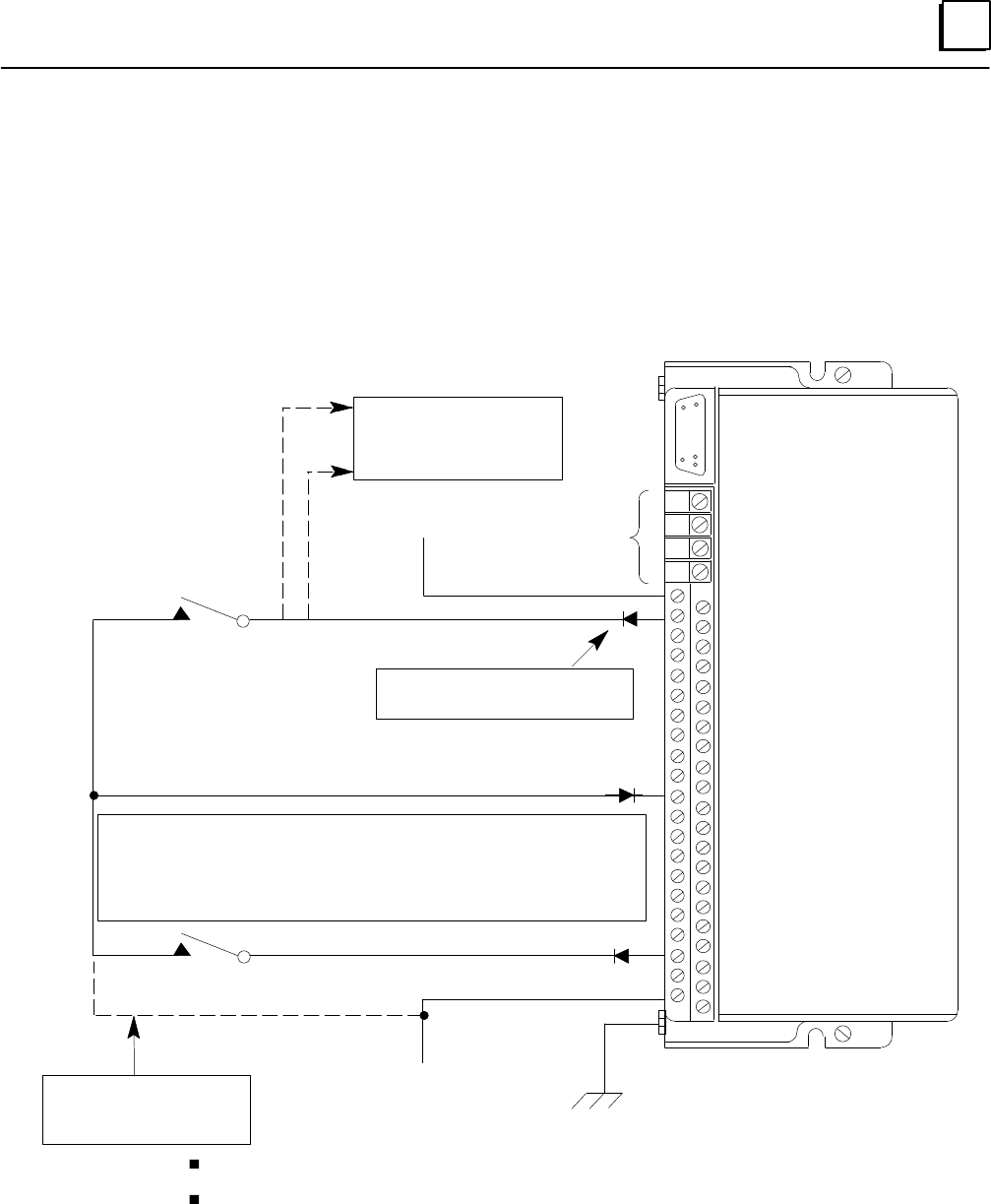
Input Wiring (continued)
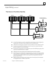
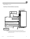
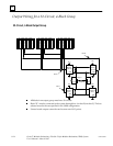
Block Wiring for 32-Circuit Sink Block in an Input Group
S1
S2
SHLD IN
SHLD OUT
+5V
DC+
DC+
DC+
DC+
10
12
14
16
18
20
22
24
26
28
30
32
34
36
38
40
42 DC–
DC–
44 DC–
DC–
46 DC–
Genius Bus
Connections
22V to 30V DC
DC Sink Block IC660BBD025
O VDC
Ground
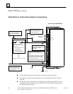
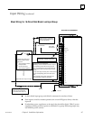
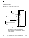
If group inputs are configured for autotesting, circuit 16 must be used as an output
If no autotesting is to be done on this group of inputs, the input devices must not be wired to
circuit 16. They must be wired to the power source instead.
If group uses single sensors, point 16 must also be wired to corresponding point on two
other input blocks
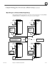
Zener diode required at each powerfeed output (for Input Autotesting). 1N5400 or equivalent.
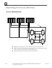
Connection if no points on the
block are to be autotested
(must disconnect output 16).
Device #1
Device #32
Output 16
If single sensor, it must also be
wired to corresponding point on
two other input blocks
Required at each input (for Input
Autotesting). 1N5400 or equivalent.
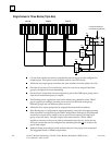
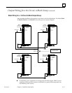
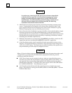
In three-block input group, each block is connected to one bus of three.
If redundant power supplies are to be used, they should be diode “ORed” power
supplies providing common power to all blocks in a group. Different groups may
use different power sources.