


8
8-11GFK-0787B Chapter 8 Installation Information
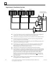
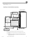
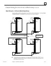
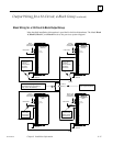
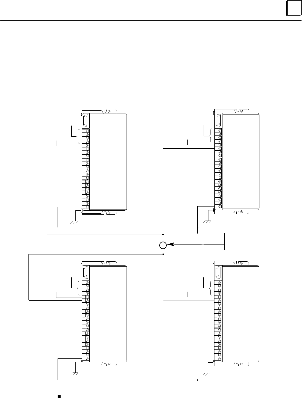
Output Wiring for a 16-Circuit, 4-Block Group (continued)
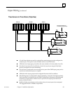
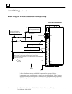
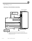
Block Wiring for a 16-Circuit 4-Block Output Group
More detailed installation information is provided in the block datasheets. The labels Block
A, Block B, Block C, and Block D refer to the previous system diagram.
S1
S2
SHLD IN
SHLD OUT
OV DC
Ground
S1
S2
SHLD IN
SHLD OUT
DC+
1
2
3
4
5
6
7
8
9
10
11
12
13
14
15
16
DC–
Bus A
Genius Bus
Connections
Ground
Load (–)
Load (100mA minimum)
Typical 16 places
+ DC Power
+ DC Power
DC+
1
2
3
4
5
6
7
8
9
10
11
12
13
14
15
16
DC–
Ground
S1
S2
SHLD IN
SHLD OUT
S1
S2
SHLD IN
SHLD OUT
DC+
1
2
3
4
5
6
7
8
9
10
11
12
13
14
15
16
DC–
Ground
+ DC Power
+ DC Power
DC+
1
2
3
4
5
6
7
8
9
10
11
12
13
14
15
16
DC–
Block C
OV DC
Load (+)
Bus B
Genius Bus
Connections
Bus C
Genius Bus
Connections
Bus A or B
Genius Bus
Connections
IC660BBD021
(Sink)
Block D
IC660BBD021
(Sink)
Block A
IC660BBD020
(Source)
Block B
IC660BBD020
(Source)
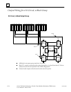
If redundant power supplies are to be used, they should be diode “ORed” power
supplies providing common power to all blocks in a group. Different groups may
use different power sources.