


A
GFT-166 Revision 1.3
April 4, 1995
A-2 Genius Modular Redundancy Flexible Triple Modular Redundant (TMR) System
User’s Manual – March 1995
GFK-0787B
TÜV Restrictions
For all safety relevant applications the safe state must be the de-energized (0) state.
A Functional test must be performed to check for the correct design and operation of the system as
a whole. This is to include the user’s application program.
No change of the system software (operating system, I/O drivers, diagnostics, etc.) is allowed
without TÜV type approval and recommissioning.
Regulations or procedures for the use of, servicing, and repair of the system with regard to the
application must be available as a part of the operational documents.
All GE Fanuc manufactured components may be used in the non-safety relevant portion of the
system if appropriately de-coupled from the safety-relevant portion of the system. Specifically
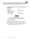
approved hardware components for the safety relevant portion are:
Catalog Number Firmware
Revision Level
Description
IC697BEM711J n/a Bus Receiver
IC697BEM713F n/a Bus Transmitter
IC697BEM731N 4.8 Genius Bus Controller
IC697CHS790D n/a 9–Slot Rack
IC697CPU788DA 5.50 GMR CPU – 100 Triplex (voted) I/O
IC697CPU789DA 5.50 GMR CPU – 2K Triplex (voted) I/O
IC697MEM735D n/a Expansion memory module 512KB
IC697PWR711CX n/a Power Supply 120/240Vac, 100 Watts
IC660BBA023K 1.4 Genius Thermocouple Input Block, 24/48Vdc
Power, 6 in
IC660BBA021K 1.1 Genius RTD Input Block, 24/48Vdc Power, 6 in
IC660BBA106K 1.0 Genius Current Source Analog Input Block,
115Vac/125Vdc, 6 in
IC660BBA026K 1.0 Genius Current Source Analog Input Block,
24Vdc, 6 in
IC660BBA024K 1.8 Genius Current Source Analog I/O Block,
24/48Vdc, 4 in/2 out
IC660BBD020M 3.6 Genius Source I/O Block, 16 circuit, 24/48Vdc
IC660BBD021M 3.6 Genius Sink I/O Block, 16 circuit, 24/48Vdc
IC660BBD024N 3.7 Genius Source I/O Block, 32 circuit, 12/24Vdc
IC660BBD025N 3.7 Genius Sink I/O Block, 32 circuit, 5/12/24Vdc
Analog input blocks that are used in the safety-relevant portion of the system must be periodically
(e.g. once per year) checked and verified manually by the application and verification of input
signals of at least 10 equally spaced points starting at the low end of the range of the input and
ending at the high end. At least two physical
points of every triplex analog input must be tested in this manner.
Simplex analog sensors can be connected to redundant analog inputs only if those analog inputs
are de-coupled by suitable devices
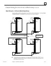
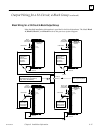
When blocks IC660BBD024 and IC660BBD025 are used as part of a redundant “H” pattern output
group, an appropriately-sized fuse must be included on each side of the load.
If Power Supply IC697PWR711CX is used with a 230 Volt AC power source, a surge protector/filter
device is required. Any incoming overvoltage transients of up to 4 Kvolts (1.2/50mS) must be limited by
this device to 2.5 Kvolts (1.2/50mS) according to VDE 0160 overvoltage category II. This device must be
installed between the power source and the power supply. 115 Volt AC power source applications do
not require a surge protector/filter device.
Each CPU module must be memory protected and the key removed.