


2
2-5GFK-0787B Chapter 2 Input Subsystem
Discrete Inputs
Types of Blocks in the Input Subsystem
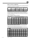
The following discrete block versions can be configured for GMR version 2.06 operation
and used as GMR input blocks:
24/48 VDC 16-Circuit Source block: IC660BBD020M or later
24/48 VDC 16-Circuit Sink block: IC660BBD021M or later
12/24 VDC 32-Circuit Source block: IC660BBD024N or later
5/12/24 VDC 32-Circuit Sink block: IC660BBD025N or later
All types of Genius blocks can be used as non-GMR blocks in a GMR system.
Note that the GMR Input Autotest feature requires point 16, so if the system uses Input
Autotest, point 16 is not available as an I/O point for the application (leaving either 15 or 31
points available on the blocks listed above).
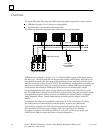
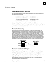
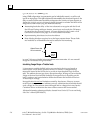
Discrete Input Processing
Discrete input processing is handled in each PLC, by the GMR system software. The
manner in which inputs are handled depends upon whether a block is included in the
GMR configuration, and if it is, upon whether it is part of a 3-block, 2-block, or 1-block
group. Input processing by the PLC is explained in detail in the PLC chapter. In general,
the GMR system software compares input data from all corresponding inputs (3, 2, or 1)
for each point, and provides a voted input result for use by the application program. If
all the input data is not available, the GMR system software follows a configured voting
adaptation scheme. The application program can also access the original, unvoted input
data, along with any non-GMR inputs that have been included in the input subsystem.
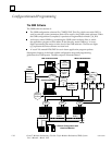
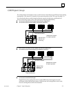
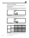
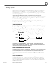
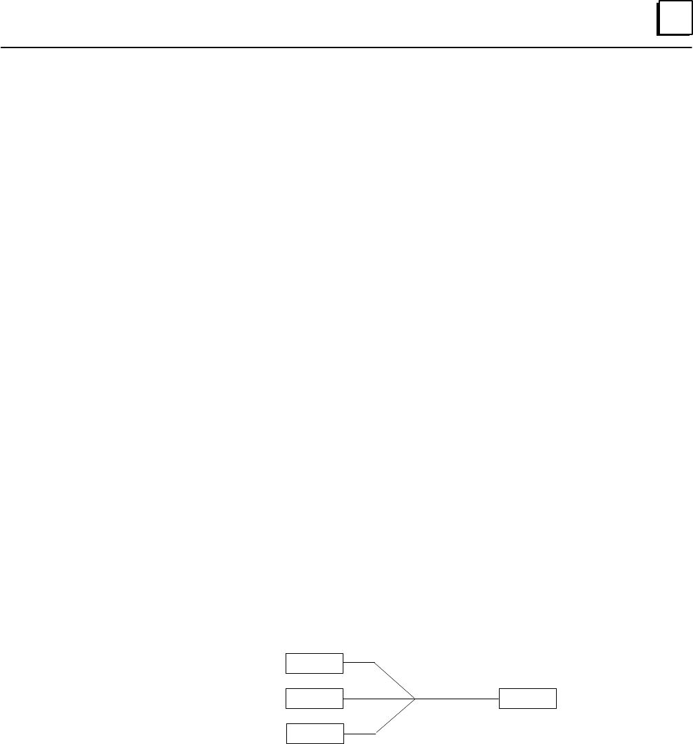
Field Input Data
Input A
Input B
Input C
0
0
1
GMR Software Performs
2 out of 3 Voting
0
Single Input Pro-
vided to Applica-
tion Logic
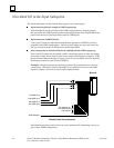
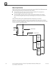
Discrepancy Reporting for GMR Inputs
For GMR inputs, if there is a discrepancy between the original input data for an input
and the voted input state, the GMR software automatically places a message in the I/O
Fault Table, where it is available to the Logicmaster 90 software and the application
program logic. This is also described in more detail in the PLC chapter. Fault bits are also
set for input discrepancies. These fault bits are available for use in the application
program, for further annunciation or corrective action.
Discrepant signals are filtered for a configurable time period, to eliminate transient
discrepancies caused by timing differences.