


2
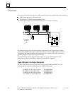
2-6 Genius Modular Redundancy Flexible Triple Modular Redundant (TMR) System
User’s Manual – March 1995
GFK-0787B
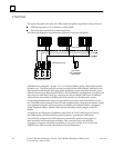
Input Autotest for GMR Inputs
During GMR configuration, input autotesting can be individually turned on or off for each
input in an input group. The GMR software will automatically test the selected inputs for the
ability to reach the alarm state. The ability to diagnose short circuits on inputs depends on
whether the circuit is set up as a bistate or tristate input, and on whether the block itself is
configured for GMR mode (using the Hand-held Monitor).
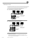
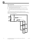
Autotesting checks the ability of the input electronics to recognize both the On and
the Off state. During each Input Autotest, some inputs are forced to the Off state by
de-energizing the power feed output, and some are forced to the On state via the
Genius block electronics. See page 5-6 for more detailed information.
Input autotesting also detects circuit-to-circuit shorts.
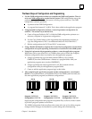
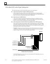
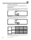
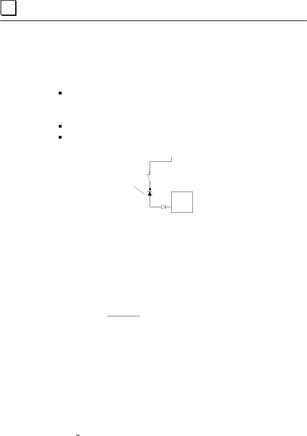
Note: blocking diodes are required to use the Input Autotest feature. These diodes
are in addition to a Zener diode that may be added for line monitoring.
Source
Genius
Block
+24V
Optional Zener diode
for line monitoring
See page 5-6 for more detailed information about input autotesting. Also see pages 8-3
through 8-9 for Autotest wiring information.
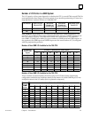
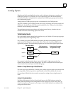
Calculating Voltage Drops on Tristate Inputs
It is important to consider the field wiring runs required for devices configured as
tristate inputs. Devices that are powered by 24V DC will have a voltage-reducing
component inserted at the field device to provide an input threshold range for three
states. The table on the next page shows appropriate ranges. Wiring runs can reduce the
voltage at the input block terminal further, to an inoperable level, depending on the
length, conductor, and gauge. Isolation diodes placed before the terminal on the input
will also drop the voltage.
Most applications do not have limitations created by these factors. However, to ensure
that all input state operations are indicated correctly, calculations should include the field
signal voltage, the wire resistance times the length and the voltage drop in any barriers
or isolation devices, to determine the actual voltage present at the input terminal.
Additional information about input blocks is located in the Genius I/O Discrete and Analog
Blocks User’s Manual (GEK-90486-2).