


3
3-7GFK-0787B Chapter 3 Output Subsystem
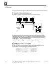
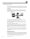
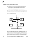
Operation of a 4-Block Output Group
Each GMR output state is sent to four blocks set up in an H-pattern as shown on the
opposite page. This type of grouping creates a fault-tolerant system where any single
point of failure does not cause the system to lose control of a critical load. This is
achieved by:
output voting (which is explained on page 3-3), and
the electrical characteristics of sink and source blocks, and
redundant busses.
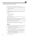
Electrical Characteristics of Sink and Source Blocks
If a load is wired between a sink and source block, both the sink output and the source
output must be active to control the load. If either the sink output or the source output
fails On, turning the other Off, turns the load Off. Doubling the number of blocks to
four and putting them in an H pattern means that if any single point of failure occurs,
the system can still control the load.
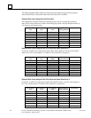
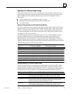
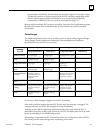
The following chart shows how the GMR system uses the 4-block H-pattern output
group to maintain control of critical loads following certain types of failures. All
operating blocks receive the same I/O data, because within a fault-tolerant 4-block
H-pattern group, all four blocks are configured at the same output address. The chart
indicates which blocks actually affect the state of the load under different fault scenarios.
All operating blocks act on the I/O data received.
Other Blocks Used Other Blocks Used
Fault To Turn the Load Off To Turn the Load On
output at block A fails On turn outputs at block C and D Off turn output at block C or D On
output at block A fails Off turn output at block B off turn output at block B and either C or D On
output at block B fails On turn outputs at block C and D Off turn output at block C or D On
output at block B fails Off turn output at block A off turn output at block B and either C or D On
output at block C fails On turn outputs at block A and B Off turn output at block A or B On
output at block C fails Off turn output at block D off turn output at block D and either A or B On
output at block D fails On turn outputs at block A and B Off turn output at block A or B On
output at block D fails Off turn output at block C off turn output at block C and either A or B On
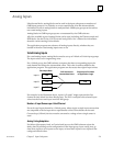
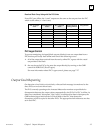
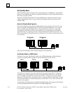
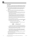
Bus Redundancy in a 4-Block Output Group
If one of the three busses in an output group is damaged or cut, there is still I/O data
communicated to at least one sink output and one source output to control the load.
When a block loses communication with all the PLCs, its outputs go to a default state. If
the default state is Off, the system is fault-tolerant as shown in the following chart.
Fault To Turn the Load Off or On
bus A fails busses B and C still provide I/O communications to blocks B, C, and D;
turning outputs at those blocks On or Off turns the load On or Off.
bus B fails busses A and C still provide I/O communications to blocks A and C; if the
block B and D outputs are configured to default Off, turning output at
blocks A and C On or Off turns the load On or Off.
bus C fails busses A and B still provide I/O communications to blocks A, B, and D;
turning outputs at those blocks On or Off turns the load On or Off.