


4
4-2 Genius Modular Redundancy Flexible Triple Modular Redundant (TMR) System
User’s Manual – March 1995
GFK-0787B
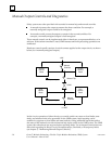
System Startup
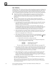
The following actions occur during orderly startup of the GMR system:
1. Each PLC disables its outputs to Genius blocks. If the Outputs Disable function does
not complete successfully, the GMR software sets the flag “GMR System
Initialization Fault” and the GMR software puts the PLC in Halt mode.
2. Each PLC determines its PLC identity: PLC A, PLC B, or PLC C.
For a PLC, all bus controllers that have been included in the GMR software configuration
must have been assigned the same serial bus address: 29, 30, or 31. Each PLC checks its
GMR configuration to be sure this has been done. If it has, the PLC determines its
identity as follows:
PLC A all GMR bus controllers at serial bus address 31.
PLC B all GMR bus controllers at serial bus address 30.
PLC C all GMR bus controllers at serial bus address 29.
If a PLC determines that its GMR bus controllers have been configured with
differing serial bus addresses, or with addresses outside the range 29–31, it logs an
“Invalid Bus Address” fault into its PLC Fault Table and stops the PLC.
3. Each PLC checks the online status of the other PLCs. “Online” means the other PLC
is running its application program, and its outputs are enabled.
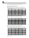
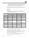
4. Each PLC compares its initial program checksum with those of the other PLCs. If
they do not match, the PLC may (as configured) either stop or keep running. The
next table compares the effects of checksum mismatches with the PLC configured to
allow or reject online program changes:
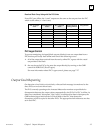
5. Each PLC compares its initial GMR configuration checksum with those of the other
PLCs. If they do not match, the PLC stops.
After successful initialization, when the application program is running, the PLC will
continuously compare its program checksum against the initial program checksum,
and if they do not match, the PLC will (as configured) either stop or keep running.
Note that if a synchronizing PLC detects that an online PLC has gone offline during
synchronization, it attempts to restart data synchronization with the other PLC. If
the other PLC is not online, the synchronizing PLC will flag that synchronization is
not possible, and halt.
6. PLC C (which uses serial bus address 29) sends an “Assign Controller” datagram to
all blocks and also sends an “Assign Monitor” datagram to the blocks configured for
Hot Standby mode to ensure correct operation with three PLCs. If this function does
not complete successfully, the GMR software places a “GMR System Initialization”
fault into the PLC Fault Table. This fault can be configured to stop initialization and
halt the PLC or allow it to continue.
7. (PLC B or PLC C) initializes data values. This is described in more detail on page 4-4.
8. The Inhibit bit is released, allowing the PLCs to start executing the application program.
9. When the Continue control flag is set by the user’s application program, the PLC
begins sending outputs computed by the application program to Genius blocks.
10. If these outputs match the current output states of the blocks, they are accepted by
the blocks. If a block detects that outputs from a PLC do not match the current