


6
6-9GFK-0787B Chapter 6 Configuration
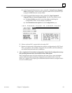
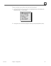
9. [Insert] the first GBC (bus controller) group
A. Select each bus controller in the group (GBC_A, GBC_B, GBC_C).
(1) Specify a rack and slot location
(2) Select [OK] or [C]ancel to quit the Rack/Slot window
B. Configure all the input and output block groups for the GBC group.
(1) [Insert] each Input block group. For each Input block group:
(a) Select the group type (triplex, duplex, simplex, discrete, analog)
(b) Configure the Input block group:
Enter an ID, starting reference address, serial bus address
Select Autotest and specify each input to be autotested and Test
Type for the block group (Sync or Async)
Select [O]K or [C]ancel to quit the Autotest window
Select VoteAdapt and specify each input for vote adaptation
Select the Duplex state (0 or 1), Default state (0/1/hold last), and Hot
Standby mode for any outputs on the block group
Select [O]K or [C]ancel to quit the VoteAdapt window
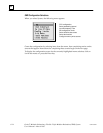
(2) [Insert] each Output block group. For each Output block group:
(a) Select the group type (16 point or 32 point)
(b) Configure the Output block group:
Enter an ID, starting reference address, serial bus address
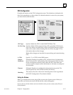
Select Autotest and specify each output to be autotested and its
normal state.
Select [O]K or [C]ancel to quit the Autotest window.
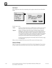
Select Options and specify the bus and bus address for the 4th block
Select [O]K or [C]ancel to quit the Options window.
10. [Insert] any additional GMR bus controller groups in the same PLC(s). Configure
each additional bus controller group as described in step 6.
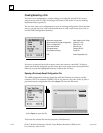
11. Save the configuration. This creates a file with the filename extension .SAV in the
selected directory (by default this is the same directory where the GMR
CONFIG.EXE software is located).
12. With the configuration file still present in the computer’s RAM memory, create the
GMR configuration output file. Select Output, then select Write Configuration
from the Output menu. This creates an output file with the filename G_M_R10.EXE.
This file is stored in the currently-selected directory.
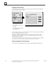
13. Print out the configuration. Select Output, then select Print Out from the Output
menu.
14. Import the configuration into your application folder as described on page 6-46.