


QUICKSTART GUIDE
UR SWITCH MODULE – QUICKSTART GUIDE QS–9
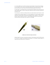
the 9/125 micrometer fiber is 8 microns in diameter (almost an eighth of that of the multi-
Mode fiber) surrounded by a second outer layer of cladding. This cladding can pass a light
signal, so for this reason the fiber is referred to as 9 by 125 micrometer fiber.
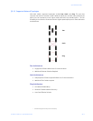
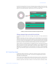
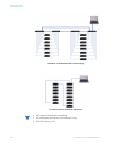
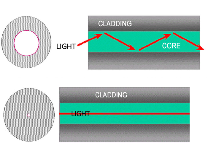
FIGURE QS–3: Differences between Multi-Mode and Single-Mode Cable
Difference between Single-mode and Multi-mode Cable
The difference between multi-mode and single mode cable can be best described as
follows:
With multi-mode fiber the index of refraction at the surface between the core and the
cladding is such that there is total internal reflection of the light being transmitted down
the core. Picture this by imagining that the clad is a tube whose interior surface is polished
so smooth, it is like a mirror. Light shinning at one end of the tube will either travel straight
down the tube or will travel down the tube by reflecting of the inner mirrored surface.
Single mode fiber can be described as an elongated lens that is continuously focusing the
light into the centre of the fiber. Using these two analogies it can be imagined that in the
single mode fiber more light travels through far less fiber medium resulting in far less
attenuation per unit distance than in multi-mode fiber. As a result, for a given wavelength
of light, single mode fiber typically has less attenuation per unit distance than multi-mode
fiber.
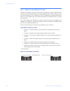
QS.3.3 Optical Power Budget
Inevitably the question that arises is, “What is the maximum practical communication
distance when using a fiber optic cable?”. The answer isn’t straightforward; it must be
calculated in the following way:
First the Optical Power Budget is determined by subtracting the receiver’s rated sensitivity
from the transmitter’s rated power, both of which are rated in decibels of light intensity. For
example, if a particular transmitter is rated at -15 db and the receiver’s sensitivity is rated