


QS–10 UR SWITCH MODULE – QUICKSTART GUIDE
QUICKSTART GUIDE
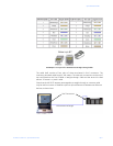
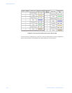
at -31 db the difference of 16 db is the Optical Power Budget. The Optical Power Budget
can be thought of as the maximum permitted attenuation of the light signal as it travels
from the transmitter to the receiver, while still permitting reliable communication.
The next step is to calculate the worst case optical power budget by subtracting from the
optical power budget, 1 dB for LED aging and 1 dB for each pair of connectors (referred to
as insertion loss).
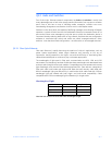
The final step is to divide the calculated result by the rated cable loss per kilometer in order
to determine the maximum distance. For costly installations it is recommended to always
measure the actual cable loss before and immediately after installation, in order to verify
that the cable was installed correctly. To avoid damaging the receiver, ensure that the
maximum optical input power of the receiver isn’t exceeded.
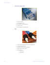
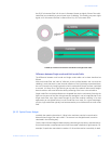
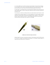
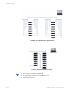
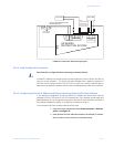
FIGURE QS–4: Common Fiber Optic Connectors
Several styles of connector are used to terminate to, and attach the end of the fiber cable.
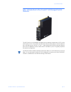
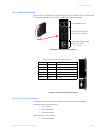
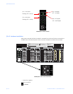
The ST and SC connectors are among the more popular. The UR Switch module supports 2
copper ports and 4 fiber ports (ST connectors).