


466-2262A • October 2006
Copyright © 2006, GE Security Inc.
SuperBus 2000 Concord 4 GSM Module
Installation Instructions
Introduction
This is the GE SuperBus 2000 Concord 4 GSM Module Installa-
tion Instructions for part number 600-1053. The module can be
used on Concord 4.0 and higher.
The module interfaces with the Concord panel data bus and is
powered by the panel battery or an auxiliary 12 VDC power
supply. Status LEDs indicate bus and paging network communi-
cations. A supervised zone input allows you to connect a hard-
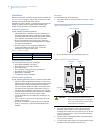
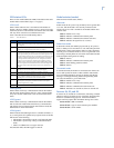
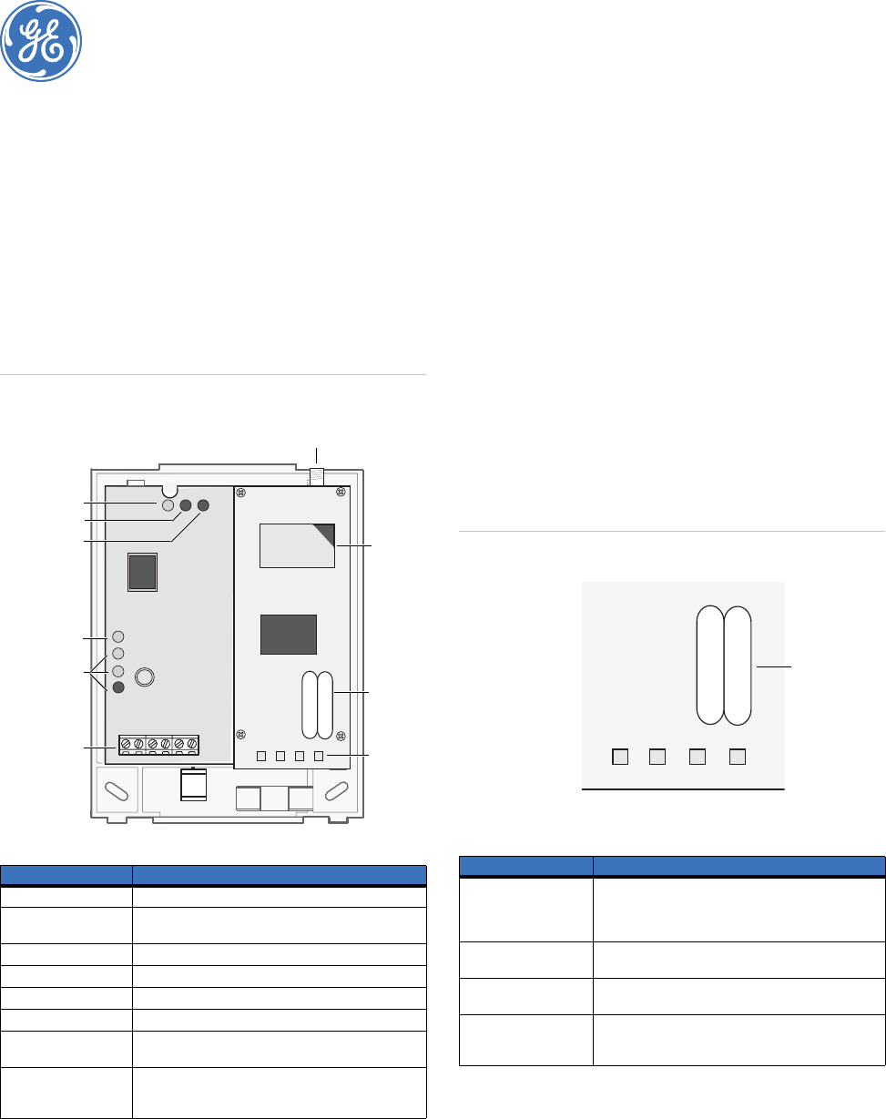
wired contact. Figure 1 shows the location of the main module
components and Table 1 describes the component functions.
Figure 1. Main module components
Installation tips
Use the following tips to help guarantee your success with the
Alarm.com Concord GSM Module:
1. Make sure you create the customer account on the
Alarm.com dealer website at least 24 hours before installa-
tion. See Account creation on page 6.
2. Make sure you turn off the Access Code Lock feature.
3. Use the LEDs on the module to check the signal strength
before you permanently mount the module.
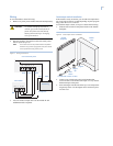
4. Power the module off of the battery (see Wiring on page 3),
not off of the panel.
5. Do a manual phone test to initiate communication (see
Power up on page 4).
GSM status LEDs
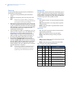
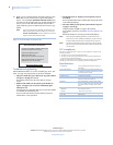
Figure 2 shows the GSM status LEDs and Table 2 describes the
LED functions. See GSM status LEDs on page 5 for more infor-
mation.
Figure 2. GSM status LEDs
Table 1. Module component descriptions
Component Function
PWR LED Indicates module power status.
BUS LED Indicates data bus activity between the panel and
module.
AUTO LED Indicates module/data transceiver communication.
Status LEDs Indicates communications status with GSM network.
Wiring terminals Provides panel and zone wiring connections.
Antenna jack Antenna connection for wireless data transceiver.
GSM status LEDs Indicates communication with the GSM network,
report errors, and signal strength.
Serial number A 15-digit number beginning with 35323900. Only the
last 10 digits, starting with 900, are used for account
activation.
Antenna
jack
PWR LED
Serial
number
label
BUS LED
AUTO LED
Unused LED
Status LEDs
Wiring
terminals
SIM
card
GSM
status
LEDs
Table 2. GSM status LEDs
LED Function
LED 1 Error LED. Will slash 1 to 8 times in a four-second
interval to indicate specific error conditions such as a
network error, panel communication error, or GSM
radio error.
LED 2 Panel communication LED. Flashes every time a data
packet is received from the panel.
LED 3 GSM communication LED. Flashes every time a data
packet is received from the GSM radio.
LED 4 GSM signal level LED. Flashes 0 to 5 times, or toggles
on/off when communicating with the Alarm.com
servers.
L1 L2 L3 L4
GSM status LEDs
Serial
number
label