


GE Zenith Controls 23
■
ZTSCT / ZBTSCT Operation and Maintenance Manual (71R-5000A)
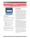
Sequence of Operation
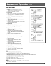
Open Transition
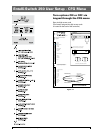
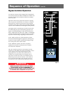
Source 1 Power Failure:
When Source 1 voltage or frequency has fallen below
the preset "Fail" values, the controller initiates the
Time Delay Source 2 Start (Engine Start Timer "P")
cycle. Upon completion of the (P) time delay, an
Engine start Signal is sent to Source 2. When Source 2
voltage and frequency reach the preset "Restore" values,
the time delay to open Source 1 timer (W) begins its
timing cycle to ensure voltage and frequency stabiliza-
tion before re-transfer. A manual pushbutton BYPASS
is provided to bypass the "W" time delay if desired.
After the (W) time delay, the MX controller initiates a
transfer signal through the SCR-NO to operate the main
transfer operator. The load is now transferred to the
Open position. The time delay to Source 2 timer (DW)
begins its timing cycle. After the (DW) time delay, the
MX controller initiates a transfer signal through the
SCR-E to operate the main transfer operator. The load
is now transferred to Source 2 line. The transfer switch
is mechanically locked. SN limit switch awaits the next
operation to Source 1.
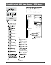
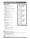
Restoration of Source 1 Power:
When Source 1 power reach the preset "Restore"
values, the controller initiates re-transfer to Source
1sequence.The delay to open Source 2Timer (T) begins
its timing cycle to ensure voltage and frequency stabilization
before retransfer. A manual pushbutton BYPASS is provided
to bypass the "T" time delay if desired. After the (T) time
delay, the MX controller initiates a transfer signal through
the SCR-EO to operate the main transfer operator. The
load is now transferred to the Open position. The time
delay to Source 1 timer (DT) begins its timing cycle.
After the (DT) time delay, the MX controller initiates a
transfer signal through the SCR-N to operate the main
transfer operator. The load is now transferred to Source
1 line. The transfer switch is mechanically locked. SE
limit switch awaits the next operation to Source 2.
Immediately after re-transfer, the S2 Stop Delay Timer
(Delay to Engine Stop "U") begins its cycle to allow
Source 2 Engine to run unloaded. A manual pushbutton
BYPASS is provided to bypass the "U" time delay if
desired. Upon completion of the (U) timing cycle, the
controller sends an Engine stop signal.
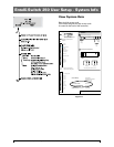
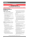
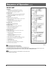
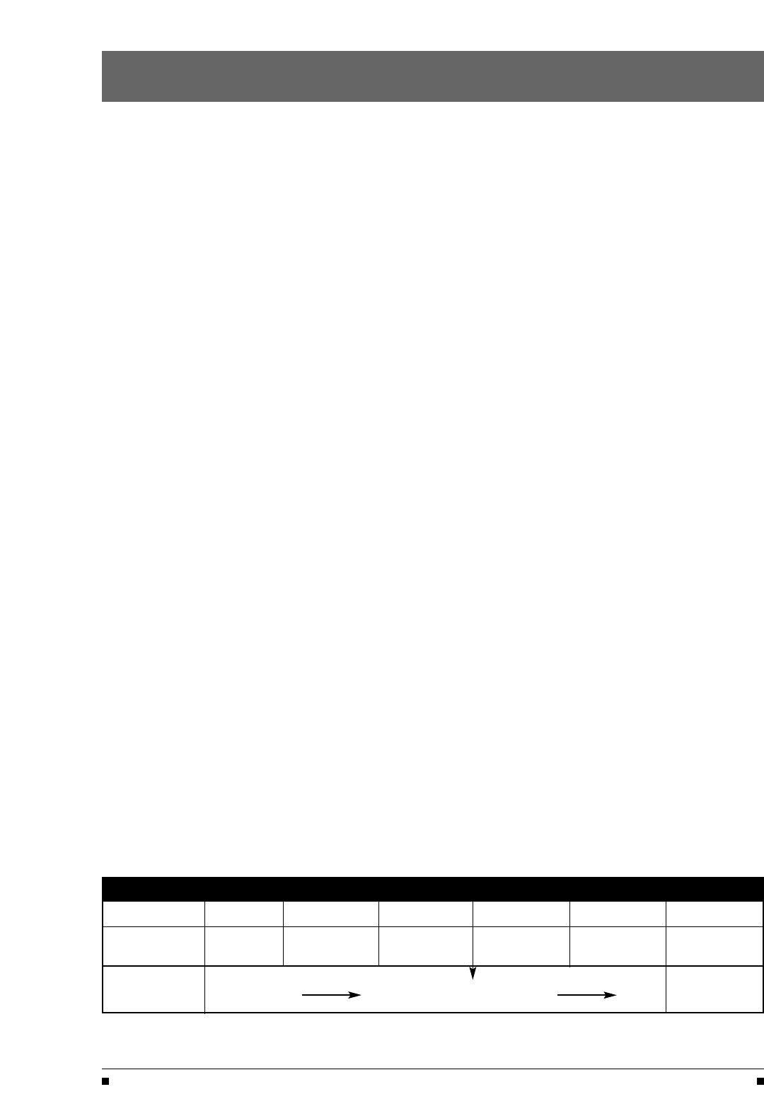
Table 3
Timer Designations as they appear in the SET menu
ATS Type P W DW T DT U
Open Time Delay Time Delay ATS Open Time Delay ATS Open S2 Stop
Transition S2 Start S2 Stable Time to S2 S1 Stable Time to S1 Delay
Source 1 Transfer to Source 2
Source 1
Transfer to Source 1 Engine
Fails
Returns
Cooldown