


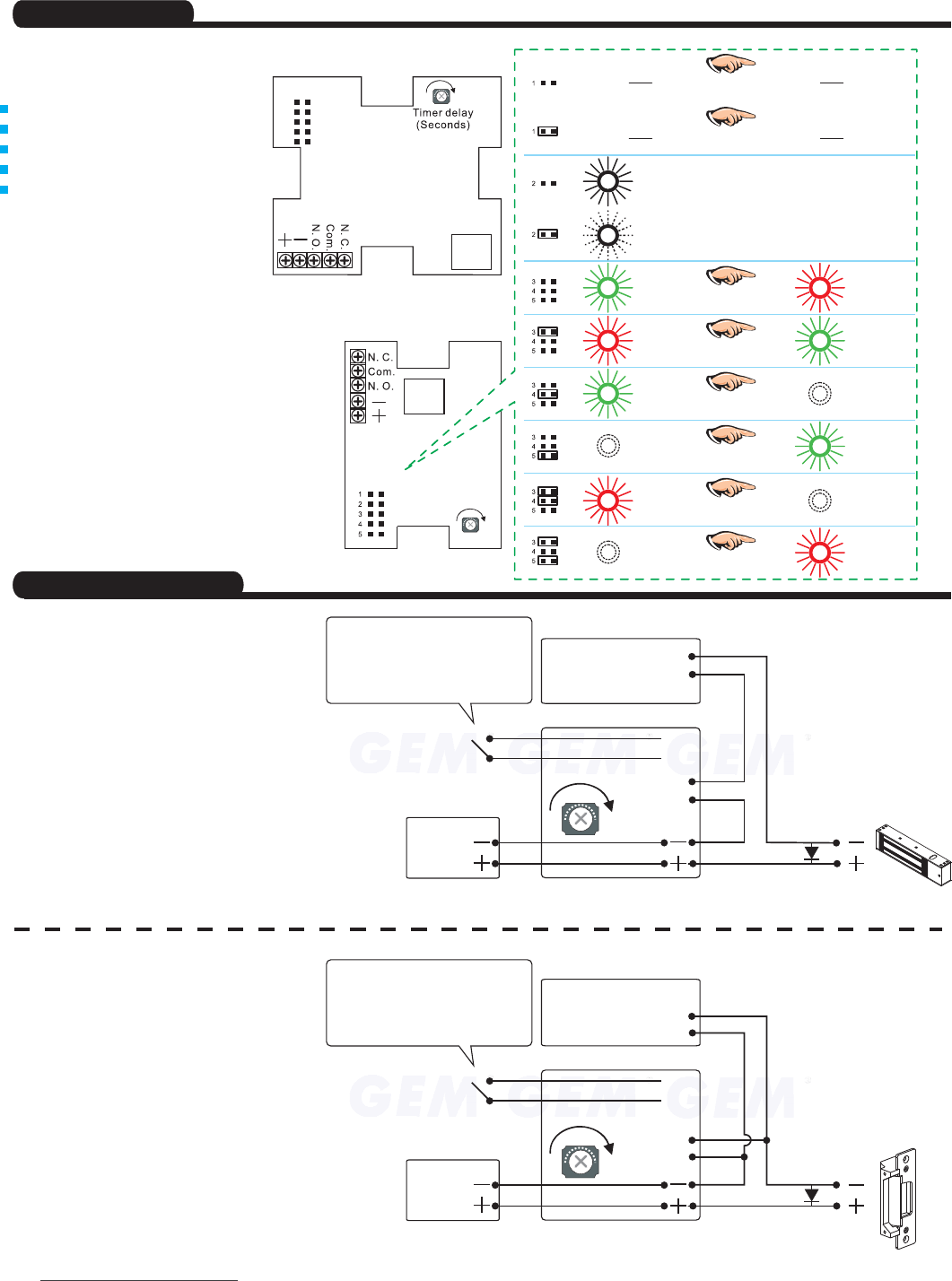
Fig. A
Fig. B
Locking Device
(fail-safe)
Locking Device
(fail-secure)
N.O.
N.O.
N.O.
N.O.
Com.
Com.
Com.
Com.
N.C.
N.C.
N.C.
N.C.
TR
TR
TR
TR
Shorten
Shorten
Power Supply
Power Supply
(Trigger)
(Trigger)
Installation Instruction
BTS Touch Sensitive Switch
Copyright 200 GIANNI INDUSTRIES,INC. Allrights reserved.
Ver. 200 . .
©8
P-MU-BTS200 L Publishedon 8 06 09
Specifications
Connecting Diagram
Control Device(Outdoor)
Control Device(Outdoor)
BTS Touch Sensitive Switch
(Indoor)
BTS Touch Sensitive Switch
(Indoor)
Relay output
control
Relay output
control
In Fig. A, BTS directly controls the release of fail-
safe(Power to Lock) locking device.
The diagrams below illustrate the two
recommended ways of installing the BTS Touch
Sensitive Switch and access control devices after
power input (power on).
In Fig. B, For fail-secure(Power to Unlock) locking
devices the contact on control device should be sat
to N.O. The relay time of BTS is the same as the
release time of locking device in both cases.
BTS-200 adds an extra
trigger for remote control
purpose; it has the same
effect as touching motion.
BTS-200 adds an extra
trigger for remote control
purpose; it has the same
effect as touching motion.
1. It is important to take extra notice on the maximum voltage and current output that the rated of relay contact to be used.
2.
IMPORTANT NOTICE:
Make sure that the "+" and "-" wire are connected correctly.
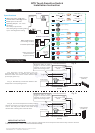
Timerdelay
(Seconds)
Setting JP
Relay
Relay contact output
(free voltage contact)
12~24VDC power input
130
Relay output model
control and LED
brightness setting
BTS-300 , 400-ANSI
BTS-486
Relayoutput
Relayoutput
Relayoutput
Relayoutput
Com. N. C.
Com. N. O.
Com. N. O.
Com. N. C.
(Touched)
(Touched)
(Touched)
(Lightis lighting)
(Lightis blinking.)
(Green)
(Green)
(Green)
(Green)
(Red)
(Red)
(Red)
(Red)
(Touched)
(Touched)
(Touched)
(Touched)
(Touched)
1
30
Relay
Setting JP
1
2
3
4
5
SPDT relay rating: 3A@ 125V~
Current: 60mA~100mA@12V DC
Power input :
Operating Temper.:
12~24 V DC
- 20~+70ºC
JP setting:
JP1: Relay output model
JP2: LED lighting or blinking setting
Jp3~5: LED brightness setting
Specifications