


These instructions apply to the field
installation of end switch kits on Greenheck
model WD Backdraft Dampers. These end
switch kits can be used in conjunction
with MP-100, MP-200, and MP-300 Series
actuators.
End switches are typically wired to a fan
and/or to a light serving as an open/not open
indicator. When the damper is powered open,
one of the damper blades makes contact with
the spring rod of the end switch which in turn
makes a connection allowing power to flow to
the fan and/or light. This set up would be used
when it is desirable to ensure that the damper
is fully open before the fan starts.
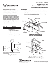
Instructions:
1. Position end switch such that the back side of damper blade trips
the spring rod.
2. Mount end switch bracket to damper frame or ductwork using
#10 x
1
⁄2 in. self-drilling sheet metal screws
Damper Frame
1
⁄2 in.-14 NPSM
Damper
Blade
Damper
Tie Bar
Damper Frame
1
⁄2 in.-14 NPSM
Damper
Blade
Damper
Tie Bar
Spring Rod
Spring Rod
2
3
3
4
1
2
3
3
4
1
End Switch Installation On
WD-100 Series Dampers
Damper Frame
1
⁄2 in.-14 NPSM
Damper
Blade
Damper
Tie Bar
Damper Frame
1
⁄2 in.-14 NPSM
Damper
Blade
Damper
Tie Bar
Spring Rod
Spring Rod
2
3
3
4
1
2
3
3
4
1
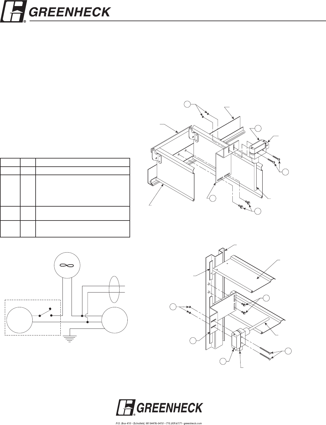
End Switch Installation On
WD-200 & 300 Series Dampers
Part Number 452723
End Switch Kit
For use on WD series Dampers
Part # Qty. Description
1 1 End switch mounting bracket
2 1 End switch
UL/CSA Rating L67
15 Amps: 125, 250, or 480 VAC
0.25 Amps: 250 VDC
0.50 Amps: 125 VDC
3 2 #6-32NC x 1½ in. machine screws with
nuts (packaged in end switch housing)
4 2 #10 x ½ in. self-drilling sheet metal
screws
Field Installation Instructions
Copyright © 2008 Greenheck Fan Corporation
#452723 End Switch Rev 3 Aug 2008
Common
L
1
Wiring Illustration
End
Switch
M
Green
Fan or
Light
N.C.
N.O.
L
2
Damper
Actuator
Wiring Illustration
Note: Some actuators are multi-tap, use correct connections per
actuator wiring diagram.