


INSTALLATION
INSTRUCTIONS
RS-232 Interface /
Serial Printer Port
K1148-X 4/98
1 2 3 4 5 6 7 8
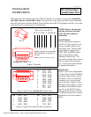
Figure 1: Connector
RJ-45
Female DB-9 Back view
21345
6789
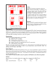
Pin DCE DTE
1 DCD DCD
2 RXD TXD
3 TXD RXD
4 DSR DTR
5 GND GND
6 DTR DSR
7 RTS CTS
8 CTS RTS
Figure 3: Signal Lines: Interface RJ-45 connector
Bl R G O Bk Y Gy/Wh Br
Figure 2: Signal Lines (Female DB-9 Front view)
Pin DCE DTE
Pin DCE DTE
1 DCD DCD
2 RXD TXD
3 TXD RXD
4 DSR DTR
5 GND GND
6 DTR DSR
7 RTS CTS
8 CTS RTS
Wire colors from RJ-45
Install crimp pins in matching
DB-9 locations as shown on
the left.
21345
6789
NOTE: Location 9 on DB-9 is empty.
The hardware in this package provides an RS-232 interface to a Destiny control panel (model Des-
tiny 6100, software version 8.04 or later). The interface can be used to provide 2-way communica-
tion with a personal computer, Remote System Mode with an RS-232 equipped controller, or to send
a real-time log of system events to a serial printer.
NOTE: Observe the drawing
and the connector used and
verify the color codes are
equivalent.
Serial Printers:
If your serial printer requires a
male 9 or 25 pin connector, you
can get a gender changer at an
electronics store. Destiny 6100
panel software supports only
GND, TXD, and RXD control
lines. Some printers require
additional control lines. You
may need to jumper these control
lines in order to use such print-
ers. Consult your printer manual
for further information.
Signal Lines:
Figure 2 shows the configuration
of signal lines in the RJ-45/DB-9
converter when wired as shown
in Figure 1. Pin 1 for the RJ-45
connector (J4) is closest to the
top of the board. Figure 3 shows
the signal lines used in a custom
installation with a DB-9 connec-
tor at J1 on the RS-232 board.
The signal lines listed on the RS-
232 Board pertain to this custom
installation, not to the standard
RJ-45.
Downloaded from - http://www.guardianalarms.net