


7. Disconnect the hard drive connector cable from the system board (see Hard drive on page 46).
8. Remove the following components:
●
Keyboard (see
Keyboard on page 49)
●
Top cover (see
Top cover on page 51)
●
USB board (see
USB board on page 58)
●
Power connector cable (see
Power connector cable on page 59)
●
Display assembly (see
Display assembly on page 62)
When replacing the system board, be sure that the following components are removed from the
defective system board and installed on the replacement system board:
●
Memory module (see
Memory module on page 45)
●
RTC battery (see
RTC battery on page 72)
●
Fan and heat sink (see
Fan/heat sink assembly on page 73)
●
Processor (see
Processor on page 80)
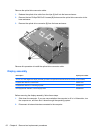
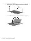
Remove the system board:
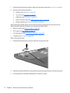
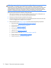
1. Disconnect the optical drive connector cable from the system board.
2. Remove the Phillips PM2.5×6.0 screw (1) that secures the system board to the base enclosure.
3. Lift the right side of the system board (2) until it rests at an angle.
70 Chapter 4 Removal and replacement procedures