


X-XX UL
INSTALLATION INSTRUCTIONS
Copyright © 1997 Honeywell Inc. • All Rights Reserved
43191680-1
05
Auxiliary Swi
tch
APPLICATION
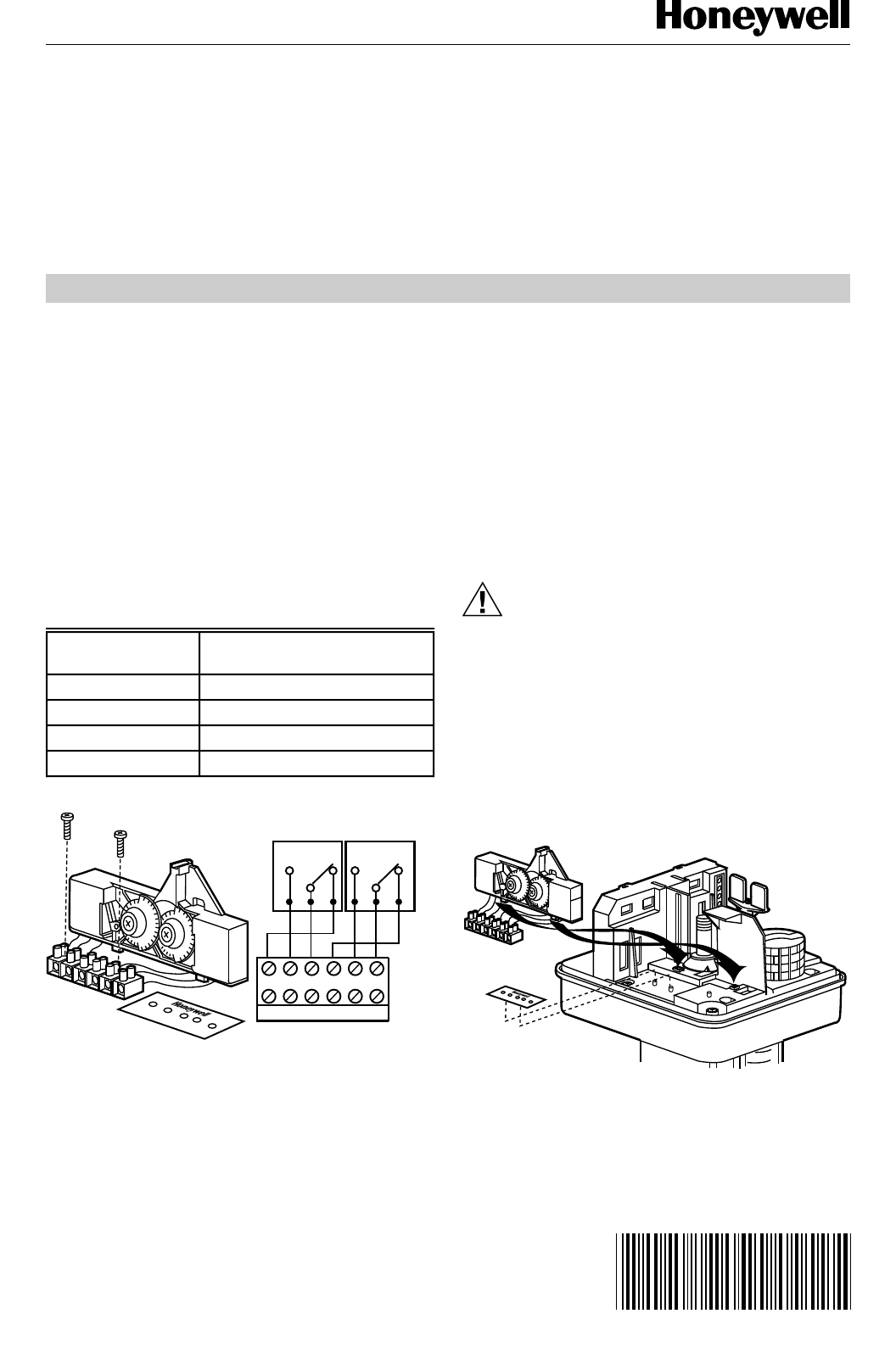
The 43191680-105 Dual Auxiliary Switch provides two
independent, spdt switching functions. Switching points
are adjustable over the full length of the actuator stroke; for
example, the switch can be used to switch pumps at any
point or to provide remote indication of any specific stroke
position. These switches are used with valve actuators as
shown in Table 1. The switches are furnished factory wired
to the terminal block. Fig. 1 illustrates the parts furnished
with this switch and the wiring connections.
IMPORTANT
These switches are rated at 24 Vac maximum.
Table 1. Applicable Actuators for
43191680-105 Dual Auxiliary Switches.
Fig. 1. Auxiliary switch parts and wiring.
6 4 5 9 7 8
C8394
1 2 3 4 5 6
SI
331122
S2
S1
S2
INSTALLATION
When Installing this Product...
ᕡ Read these instructions carefully. Failure to follow
them could result in the equipment not operating
properly.
ᕢ Check the part numbers in the preceding section to
be sure that the product is suitable for your applica-
tion.
ᕣ The installer must be a trained, experienced service
technician.
ᕤ After completing installation, use these instructions
to check product operation.
CAUTION
Disconnect the power supply to the auxiliary
potentiometer and actuator before beginning
installation to prevent electrical shock or equip-
ment damage.
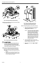
Mounting, Connecting, and Adjusting
ᕡ Remove actuator cover.
ᕢ Mount the auxiliary switch assembly and terminal
label on the actuator base. Make sure the two tabs
on the bottom of the switch assembly slip snugly into
the slots provided. See Fig. 2.
Fig. 2. Installing auxiliary switch assembly.
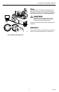
ᕣ Secure auxiliary switch assembly by pressing top
back until assembly snaps into place. See Fig. 3.
S1
S2
C8393
6 4 5 9 7 8
63-2524
Actuator
Spring Action on
Power Failure
ML6425A Extends stem
ML6425B Retracts stem
ML7425A Extends stem
ML7425B Retracts stem