


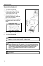
Figure 5.
Figure 7.
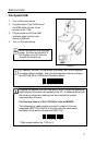
Figure 6.
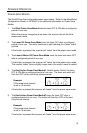
Figure 8.
INTRODUCTION
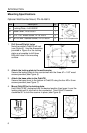
Mounting Specifications
Optional Wall/Counter Mount, PN 45-45619
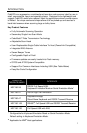
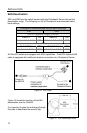
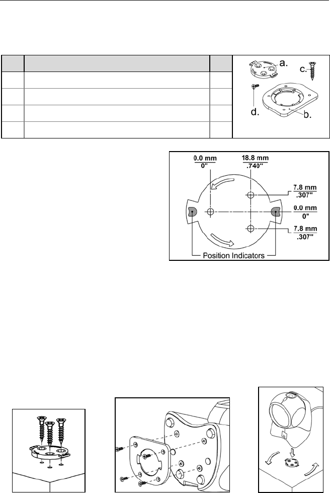
Item
Description Qty.
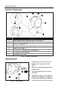
Figure 4. Kit Components
a. Locking Plate, PN 50-50302 1
b. Base Cover, PN 50-50301 1
c. #7 x 1.00" Wood Screw, PN 18-18013 3
d. M3 x 8 mm Flathead Screw, PN 18-18004 4
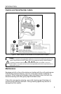
1. Drill three #39 pilot holes.
Note the position OrbitCG will rest
(see Figure 5). Use the dimensions
provided in Figure 5 or the locking
plate as a template to drill three
#39 pilot holes in the mounting
surface.
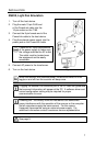
2. Attach the locking plate to the wall/counter.
Secure the locking plate to the counter/wall with the three #7 x 1.00" wood
screws provided (see Figure 6).
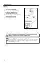
3. Attach the base plate to the OrbitCG.
Secure the base cover to the bottom of OrbitCG using the four M3 x 8 mm
screws provided (see Figure 7).
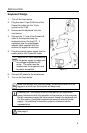
4. Mount OrbitCG to the locking plate.
Hold OrbitCG 90° clockwise from the desired position then lower it over the
locking plate until it sits flush to the countertop. Twist OrbitCG counter
clockwise 90° to lock the scanner in place (see Figure 8).
6