MICRO SWITCH Sensing and Control
MOUNTING
• E6 (side mount) and V6 (flange mount): #6
screws (#8 available on certain listings). E6
enclosures meet NEMA 1; V6 enclosures meet
NEMA 1 and 3*.
• BZG/H; #10 screws. Enclosures meet NEMA 1,
3*, 4*, 13*.
• Side and bottom mounting available. Side mount
from either side.
1. Mount switches on flat, rigid surface.
2. Sealed, side mounted: Use sealing washers
under screw heads on one side; between switch
and mounting surface on other side.
3. Unsealed, side mounted: Use lockwashers
under screw heads on one side; under nut on
other side.
4. Connect conduit to complete seal.
*Except Q plungers.
REPLACEMENT PARTS
Basic switch: order according to catalog listing on
basic switch being replaced. Replacement packet
includes basic switch, mounting hardware, seal
boot and bands where required.
Actuators or Accessories
Part Listing
N2 actuator (roller lever) 6PA2
Q2 actuator (roller lever) 6PA1
N28 actuator (one-way roller lever) 6PA16
Q28 actuator (one-way roller lever) 6PA41
N62 Actuators (rod lever) 6PA140-E6
Q62 Actuators (rod lever) 6PA62
N4 Actuators (manual button) 6PA9
Q4 Actuators (manual button) 6PA7
N18 Actuators (spring) 6PA195
N18 Actuators (spring and bushing) 6PA187-E6
Conduit Seal 2PA1
2PA6
2PA16
Seal Boot (black elastomer) 10PA2
Seal Boot (orange silicon) 10PA1
Bottom Cover E6 3PA13-E6
Bottom Cover V6 3PA14-V6
Pilot Light for BZG/H 15LT1
WIRING
Connect grounding screw or lug.
Solderless connections:
1. Use only insulated connectors.
2. Position connectors to provide as much spacing
as possible.
1.
Do not
drill or machine housing.
2.
Do not
lubricate any internal part of switch.
3.
Do not
allow internal conduit condensation to
drain into switch.
4.
Do not
enlarge mounting holes.
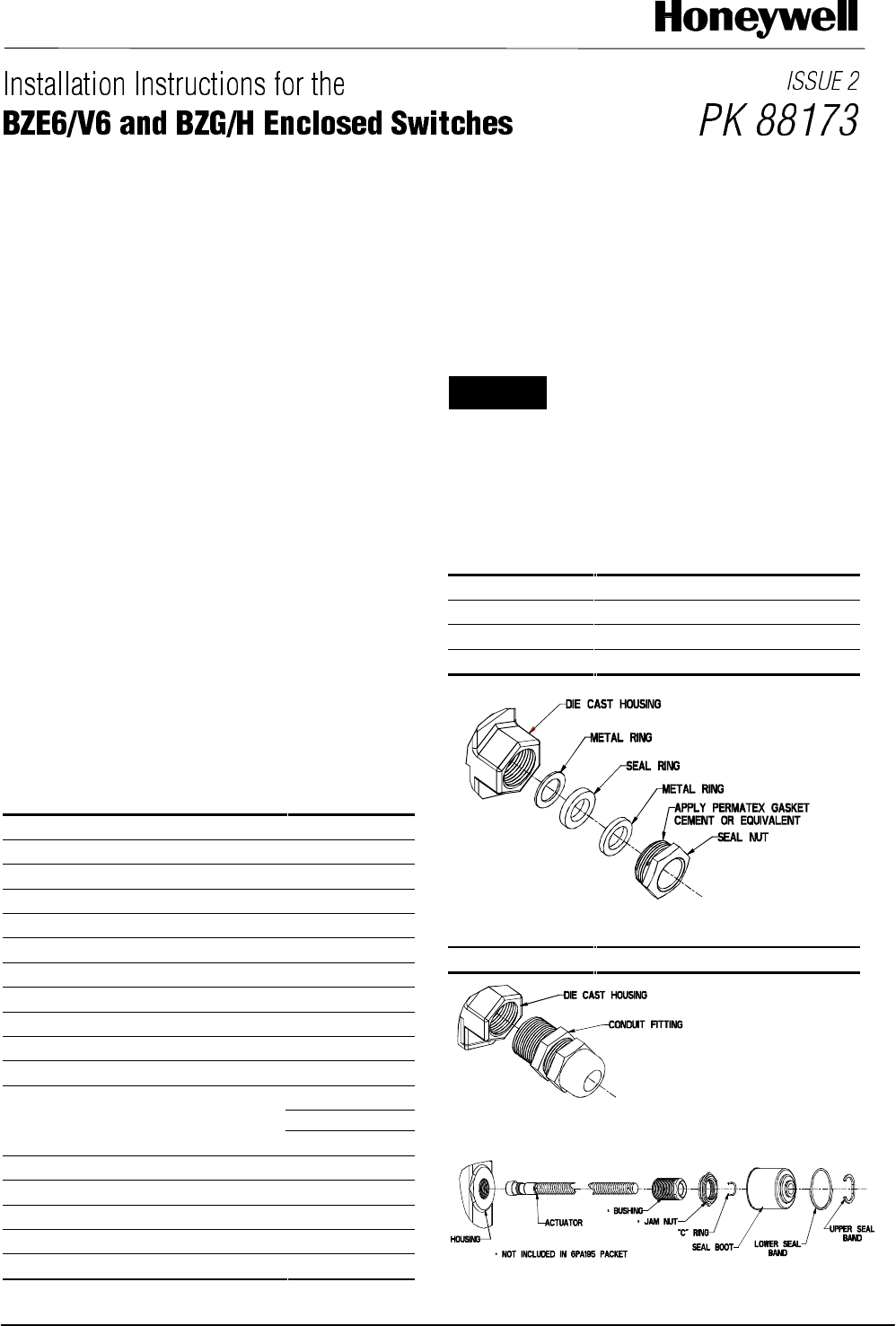
CONDUIT SEALING PACKETS
Packet Listing
2PA6
.400 - .435 (10,2 - 11,1)
2PA16
.435 - .470 (11,1 - 12,0)
2PA1
.530 - .570 (13,5 - 14,5)
LIQUID TIGHT CONDUIT FITTING
2PA17
.170 - .470 (4,3 - 12,0) 1/2 NPT
6PA187-E6 ACTUATOR PACKET


