INSTRUCTIONS
2020
Publication No. 132
January 1985
Hubbell Industrial Controls, Inc.
Repl.: January 1984
EUCLID™ PBP PENDANT
PUSHBUTTON STATIONS
ASSEMBLY AND PARTS INFORMATION
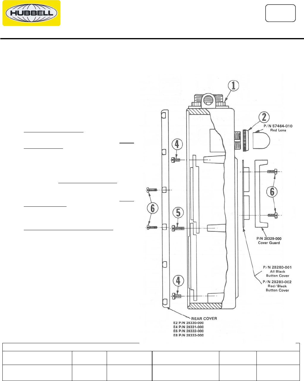
Step #1 Position hanger bracket (Item 1) as required and
tighten locking nut 1/3 turn past finger tight.
Step #2 Pilot light assembly (Item 2) if used -- push out plug
(P/N 28338) from rear. Insert light assembly. Insert
pilot light legend plate. Install locking ring.
Step #3 *Install button assembly (not Pictorially shown).
Align keying tabs and holes and press push button
assembly into terminal boards. Tighten hold down
screws. (Not used on MS2 & MS5). AVOID
OVERTIGTENING
Step #4 *Install terminal board with button assembly working
from top to bottom. Use 8-32 x 1/2" (P/N 47661-
098) "sems" screws (Item 4) where single thickness
terminal board is fastened. Observe "Top" marking
on each board. AVOID OVERTIGHTENING
Step #5 *Use 8-32 x 5/8" (P/N 47661-100) "sems" screws
(Item 5) where two terminal boards overlap. AVOID
OVERTIGHTENING
Step #6 Use 8-32 x 1/2" (P/N 47243-059) pan head screws
(Item 6) to install button guards and back cover.
CAUTION: DO NOT OVERTIGHTEN THESE
SCREWS. Recommended torque is 10 in. lbs. To
12 in. lbs. Maximum. A slight rubber bulging is
allowed.
* Where direct wired push buttons are used,
Steps #3, #4, & #5 do not apply.
PILOT LIGHTS
DESCRIPTION
CATALOG
NUMBER
LAMP
PART NO.
DESCRIPTION
CATALOG
NUMBER
LAMP
PART NO.
Pilot Light 120v 60 Hz AC
Pilot Light 240v 60 Hz AC
PL1
PL2
57465-015
57465-015
Pilot Light 120V DC
Pilot Light 240v DC
PL3
PL4
57465-043
57465-007


