


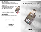

ICE 5500
Plus
Terminal
The Hypercom
®
epic (ePOS-infocommerce™) ICE™ 5500
Plus
combines the flexibility of a full
featured, smart-card ready (HyperSmart™) integrated POS terminal with the infrastructure to quickly
and cost-effectively integrate new applications. This combination makes ICE (Interactive Consumer
Enviroment) the simplest and most innovative POS solution available today. The ICE 5500
Plus
incorporates the new integrated modem technology, Hypercom FastPOS™. Operating at 9600 bps,
FastPOS allows for lower transaction costs, new data-rich applications such as signature capture, and
faster transactions.
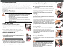
Installation Procedures
Note: The following equipment warnings are for your safety and that of your equipment.
Powering Up the Terminal
Use the following procedure to power up the ICE 5500
Plus
:
1. Connect the +24-VDC power cable from the AC adapter to the
three-pin terminal power socket on the back panel of the ICE 5500
Plus
.
See Figure 1.
2. Plug the adapter into a grounded AC power outlet. Be sure the
connector is firmly seated. When the power is properly connected the
terminal beeps twice then performs a self-test routine.
Connecting the Telephone Line
Use the following procedure to connect a telephone line to the ICE 5500
Plus
:
1. Insert the telephone cable shipped with the ICE 5500
Plus
terminal into a
dedicated analog telephone outlet.
2. Insert the other end of the telephone cable into the port labeled LINE on
the back panel of the ICE 5500
Plus
terminal and make sure it is fully seated.
See Figure 2. The use of a different cable may result in improper operation.
Note: Ensure that the telephone line cable latches are firmly locked into the
jacks on both the ICE 5500
Plus
terminal and wall receptacle.
Installing an Optional Line Splitter
If connection to an extension telephone is needed, use the following
procedure to install a Hypercom Line Splitter:
Note: The terminal disconnects the PHONE port when a transaction is
being processed.
1. Insert the Line Splitter into the terminal port labeled LINE. See Figure 2.
2. Insert the line from the extension phone into the port labeled PHONE
on the Line Splitter. See Figure 3.
3 Insert the line from the wall receptacle into the port lableled LINE.
See Figure 3.
Loading Paper
Use the following procedure to load paper into the ICE 5500
Plus
terminal:
Note: Use only thermal roll paper.
1. Squeeze the paper cover tabs and lift open the paper cover. See Figure 4.
2. Place the paper roll into the holder so the paper feeds from under the roll.
Pull the end of the paper roll over the printer. See Figure 5.
3. While holding the end of the paper roll, close the paper cover. See Figure 5.
You will hear the paper cover click when properly latched. See Figure 4.
4. Tear off the excess paper.
Attaching the Stylus
Use the following procedure to attach the Stylus to the ICE 5500
Plus
:
1. Peel the paper backing from the Stylus holder. See Figure 6.
2. Press the Stylus holder on the desired position. Hypercom recommends
placing the Stylus on the side of the paper holder, or on the body of the
terminal. See Figure 7.
Note: Only use the provided Stylus on the screen display.
Cleaning the ICE 5500
Plus
Use the following procedure to clean the casing and the printer mechanism
of the ICE 5500
Plus
:
-Apply denatured alcohol or a Windex
®
-type product to a clean, soft
non-abrasive, low-lint cloth. Carefully wipe the entire terminal,
including the touch screen and keypad.
-As needed, use anti-static compressed air to clean in and
around the printer mechanism
W
ARNING
:
•
Do not use an ungrounded adapter, power adapter, power extender cable, or AC outlet.
•
Do not disassemble the AC adapter. Only qualified technicians may service the adapter.
•
The AC adapter is intended for indoor use only; do not expose to rain or snow.
•
Do not immerse in fluid.
•
The reliability of this equipment is significantly reduced when it is powered from
an ungrounded AC power outlet.
•
Ensure that the telephone line is disconnected when the unit is unplugged from the AC
power outlet.
•
Do not use a pen on the screen display. Pens and other sharp objects will scratch or
damage the screen display.
Power
Figure 1
Figure 2
W
ARNING
: DO NOT insert the telephone line into the PIN pad port.
Paper Cover Tabs
Figure 4
Paper Roll
Figure 5
Line
RS-232
PIN
Figure 6
Paper Backing
Stylus Holder
Figure 7
Stylus Holder
Paper Holder
W
ARNING
: DO NOT use undiluted ammonia, or abrasive cleaners.
Line Port
Phone Port
Figure 3