


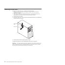
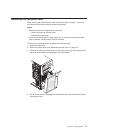
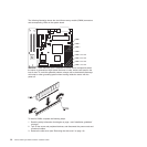
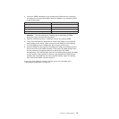
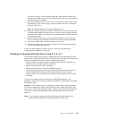
4. Locate the DIMM connectors on the system board. Determine the connectors
into which you will install the DIMMs. Install the DIMMs in the sequence shown
in the following table.
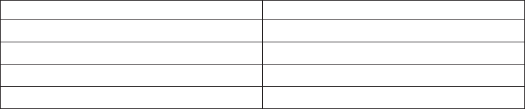
Number of DIMMs Connector sequence
One DIMM 1
Two DIMMs (interleaved configuration) 1, 3
Three DIMMs Not supported
Four DIMMs (interleaved configuration) 1, 3, 2, 4
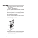
Attention: To avoid breaking the retaining clips or damaging the DIMM
connectors, open and close the clips gently.
5. Open the retaining clips and, if necessary, remove any existing DIMM.
6. Touch the static-protective package that contains the DIMM to any unpainted
metal surface on the server. Then, remove the new DIMM from the package.
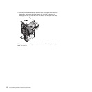
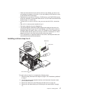
7. Turn the DIMM so that the DIMM keys align correctly with the slot.
8. Insert the DIMM into the connector by aligning the edges of the DIMM with the
slots at the ends of the DIMM connector. Firmly press the DIMM straight down
into the connector by applying pressure on both ends of the DIMM
simultaneously. The retaining clips snap into the locked position when the DIMM
is firmly seated in the connector. If there is a gap between the DIMM and the
retaining clips, the DIMM has not been correctly installed. Open the retaining
clips, remove the DIMM, and then reinsert it.
If
you have other options to install or remove, do so now; otherwise, go to
“Completing the installation” on page 28.
Chapter 2. Installing options 15