


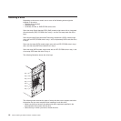
to the left to remove it from the drive cage; then, snap the drive retainer clip
into the screw holes on the side of the drive (the blue side of the drive retainer
clip should be facing outward).
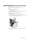
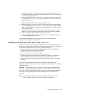
9. If you are installing a 5.25-in. drive in bay 2, push the drive into the bay. If you
are installing a 3.5-in. drive in bay 2, you must attach the 5.25-in. conversion
kit to the 3.5-in. drive.
Note: An optional diskette drive can be installed in bay 3.
10. Determine whether the drive is an IDE or SATA device; then, connect one end
of the applicable signal cable into the rear of the drive and make sure that the
other end of this cable is connected into the applicable IDE or SATA connector
on the system board.
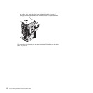
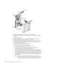
11. Route the signal cable so that it does not block the airflow to the rear of the
drives or over the microprocessor and dual inline memory modules (DIMMs).
12. If you have another drive to install or remove, do so now.
13. Connect the power cable to the rear of the drive. The connectors are keyed
and can be inserted only one way.
If
you have other options to install or remove, do so now; otherwise go to
“Completing the installation” on page 28.
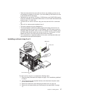
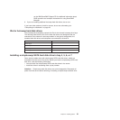
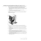
Installing a hot-swap hard disk drive in bay 4, 5, 6, or 7
This procedure applies only to server models that have hot-swap hard disk drives.
Some server models come with SAS or SATA hot-swap hard disk drives. Before you
install a hot-swap hard disk drive, read the following information:
v The hot-swap drives must be either all SAS hard disk drives or all SATA hard
disk drives; the two types cannot be combined.
v Inspect the drive tray for signs of damage.
v Make sure that the drive is correctly installed in the tray.
v To maintain proper system cooling, do not operate the server for more than 10
minutes without either a drive or a filler panel installed in each drive bay.
v You do not have to turn off the server to install hot-swap drives in the hot-swap
drive bays.
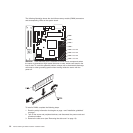
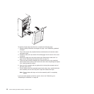
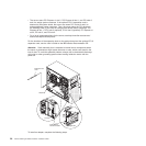
The
server hot-swap bays are connected to a SAS/SATA backplane. This
backplane, also known as the hot-swap-drive backplane, is the printed circuit board
behind these bays.
Attention: Static electricity that is released to internal server components when
the server is powered-on might cause the server to stop, which could result in the
loss of data. To avoid this potential problem, always use an electrostatic-discharge
wrist strap or other grounding system when working inside the server with the
power on.
Note:
If you install the maximum number of hot-swap hard disk drives (four),
remove the EMC shield that is attached inside the lower bezel.
Chapter 2. Installing options 19