


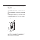
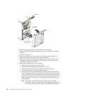
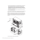
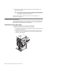
7. Pull the loops of the drive assembly toward each other; then, carefully slide the
drive assembly into the drive bay until it stops and release the loops.
Note: Do not release the loops on the drive assembly until it is completely
seated.
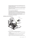
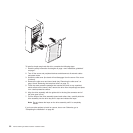
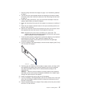
8. Attach the signal cable to the drive:
a. Attach one end of the signal cable to the corresponding connector on the
rear of the drive.
b. Attach the other end of the signal cable to the corresponding connector on
the system board.
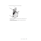
9.
Connect the power cable to the rear of the drive. The connectors are keyed and
can be inserted only one way.
If
you have other options to install or remove, do so now. Otherwise, go to
“Completing the installation” on page 28.
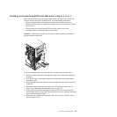
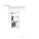
Power and signal cables for internal drives
The server uses cables to connect parallel IDE, simple-swap SATA, and SAS
devices to the power supply and to the system board. (For the location of the
system-board connectors, see the User’s Guide on the IBM xSeries Documentation
CD.) Review the following information before connecting power and signal cables to
internal drives:
v The drives that are preinstalled in the server come with power and signal cables
attached. If you replace any drives, remember which cable is attached to which
drive.
v When you install a drive, make sure that one of the signal cable drive connectors
is connected to the drive and that the connector at the other end of the signal
cable is connected to the system board.
v If you have only one IDE device on a cable, it must be set as a master device.
v If two IDE devices are used on a single cable, one must be designated as the
master device and the other as the subordinate device; otherwise, the server
might not recognize some of the IDE devices. The master and subordinate
designation is determined by switch or jumper settings on each IDE device.
The following cables are provided:
v Power cables: Four-wire power cables connect the drives to the power supply.
At the end of these cables are plastic connectors that can be attached to
different drives; these connectors vary in size. Use either a four-wire power cable
or SATA power cable with SATA drives, but do not use both at the same time
(use one or the other).
v Signal cables: Signal cables are typically flat cables, also called ribbon cables,
that connect parallel IDE, SATA, SAS, and diskette drives to the system board.
Two or three types of signal cables come with the server:
– IDE: The wider IDE signal cable has three connectors. One of these
connectors is attached to the drive, one is a spare, and the third is attached to
the primary or secondary IDE connector on the system board. The spare
connector can be used to connect an additional IDE drive to the server.
The CD-ROM drive is attached to an ATA 100 signal cable. ATA 100 signal
cables are color-coded. The blue connector is attached to the system board.
The black connector is attached to the master IDE device. The gray middle
connector is attached to the subordinate IDE device.
24 xSeries 206m Types 8485 and 8490: Installation Guide