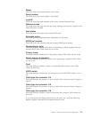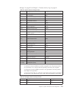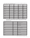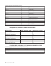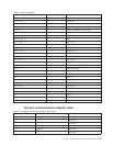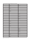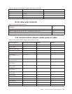
Table 47. Single-port communications adapter card wrap connector (continued). This adapter wrap connector is also
used for the 25-pin D shells on the two port adapter cable.
Communications adapter
card wrap connector Connector pin
V.24-RS232 adapter
card X.21 adapter card V.35 adapter card
9 to 11,17 9 DCERS Not Used CD
10 cable ID 2 10 CID 2 CID 2 CID 2
11 to 9,17 11 STBY DCLK-A CTS
12 cable ID 1 12 CID 1 CID 1 CID 1
13 cable ID 0 13 CID 0 CID 0 CID 0
14 to 21,22 14 Not Used Not Used DX-B
15 to 23 15 TCLK IND-B DSR
16 to 8,18 16 Not Used Not Used TX-A
17 to 9,11 17 RCLK SET-A RTS
18 to 8,16 18 WRAP DCLK-B DX-A
19 to 24,25 19 Not Used Not Used Not Used
20 to 6 20 DTR CTL-A Not Used
21 to 14,22 21 RLB Not Used RX-B
22 to 14,21 22 RI Not Used TX-B
23 to 15 23 RATE CTL-B DTR
24 to 19,25 24 DTE Not Used Not Used
25 to 19,24 25 TI Not Used Not Used
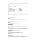
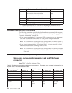
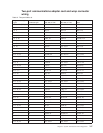
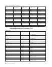
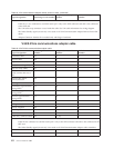
High speed communications card and wrap connector wiring
Table 48. High speed communications
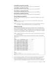
Wrap connector pin to pin Connector pin Signal destination
4to5,8 4 RTSAtoCTSA,CDA
5to4 5 CTSAtoRTSA
7 to 9, 43, 49, 50 7 SGND to CID 0, CID 1, CID2, CID 3
8to4 8 CDAtoRTSA
9to7 9 CID0toSGND
10 to 12, 40 10 DTE clock A to RCLK A, TCLKA
11 to 14 11 RI to Remote loop back
12 to 10 12 RCLK A to DTE clock A
14 to 11 14 Remote loop back to RI
15 to 45 15 Local loop back to test indicator
18 to 37 18 TD A to RD A
20 to 34 20 RD B to TD B
21 to 22, 25 21 RTS B to CTS B
22 to 21 22 CTS B to RTS B
25 to 21 25 CD B to RTS B
27 to 29, 41 27 DTE clock B to RCLK B, TCLK B
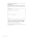
28 to 47 28 RSGND to TSGND
Chapter 9. System Architecture and Configuration 245


