


OPERATOR’S MANUAL
PE10X-XXX-XXX-XXXX
PE15X-XXX-XXX-XXXX
PE20X-XXX-XXX-XXXX
PE30X-XXX-XXX-XXXX
INCLUDING: OPERATION, INSTALLATION & MAINTENANCE
RELEASED: 3-26-13
(REV. B)
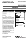
ELECTRONIC INTERFACE
for Diaphragm Pumps
READ THIS MANUAL CAREFULLY BEFORE INSTALLING,
OPERATING OR SERVICING THIS EQUIPMENT.
It is the responsibility of the employer to place this information in the hands of the operator. Keep for future reference.
INGERSOLL RAND COMPANY LTD
209 NORTH MAIN STREET – BRYAN, OHIO 43506
(800) 495-0276 FAX (800) 892-6276 © 2013 CCN 46750816
www.ingersollrandproducts.com
PUMP DATA
PE10X-XXX-XXX-XXXX is PE series 1” EXP Diaphragm Pumps with
electronic interface
PE15X-XXX-XXX-XXXX is PE series 1- 1/2” EXP Diaphragm Pumps
with electronic interface
PE20X-XXX-XXX-XXXX is PE series 2” EXP Diaphragm Pumps with
electronic interface
PE30X-XXX-XXX-XXXX is PE series 3” EXP Diaphragm Pumps with
electronic interface
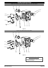
GENERAL DESCRIPTION
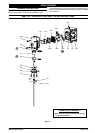
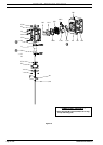
This manual is supplemental information for the electronic
interface options on the PE series of pumps. For complete
pump installation, disassembly and reassembly, safety infor-
mation, and other general pump information, please refer to
the PD pump manual that was also included with the pump.
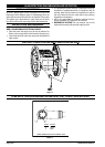
This electronic interface includes options for solenoid control,
end of stroke feedback, leak detection (diaphragm failure),
cycle counting on the major valve, and a ported motor with
no major valve for user-supplied control directly to the two
diaphragm air chambers.
Solenoid control allows the cycle rate of the pump to be con-
trolled electronically.
With Solenoid control, when the solenoid is energized, the
pump strokes and dispenses the uid in one chamber. When
the solenoid is de-energized, the pump strokes in the oppo-
site direction, dispensing the uid in the other chamber.
By providing continuous ON - OFF signals to the solenoid, the
uid transfer rate may be increased or decreased remotely.
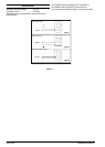
End of stroke feedback can be used in conjunction with the
solenoid valve to cycle the pump based upon completion of
each stroke.
The leak detection option incorporates an optical uid sensor
in each air chamber to provide a signal when a diaphragm
has failed and uid is leaking through the pump.
The cycle counter option provides a closed contact output
each time the pump completes a cycle. This option is not
available combined with solenoid control.
The ported motor with no major valve is provided as an op-
tion for users who want to supply compressed air directly to
each diaphragm and control the operation of the pump with
their own external air controls
.
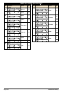
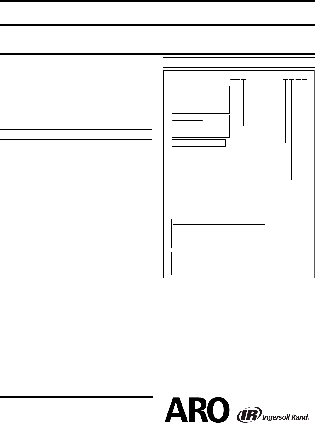
MODEL DESCRIPTION CHART
PEXX X
-XXX-XXX
-X
X
X
X
Pump Size
10 - 1” EXP Diaphragm Pumps
15 - 1- 1/2” EXP Diaphragm Pumps
20 - 2” EXP Diaphragm Pumps
30 - 3” EXP Diaphragm Pumps
Center Section
A - Aluminium
R - Polypropylene
S - Stainless Steel
Revision Level
Specialty Code 1 (Blank if no Speciality Code
)
B - Solenoid 12VDC
D - Solenoid 24VDC
A - Solenoid 120VAC
C - Solenoid 240VAC
G - Solenoid 12VDC ATEX
H -
Solenoid 24VDC ATEX
K - Solenoid 220VAC ATEX
N - Solenoid with no coil
P - Ported Motor (no major valve provided)
S - Cycle Sensing on Major Valve
0 -
Standard Valve Block ( No Solenoid)
Specialty Code 2 (Blank if no Speciality Code
)
F - End of stroke feedback
E - End of stroke feedback + Leak Detection
L - Leak Detection
Special Testing
Testing for special testing options, please contact your
nearest ARO Customer Service Representative or Distributor.
0 - No Option