


Motherboard Description
23
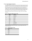
1.12.1.1 SW_ON
This 2-pin header connects to a front panel power switch. When the switch is closed, the power
supply turns on. If a mechanical switch is connected to this header, it must apply a momentary
ground to the SW_ON header pin in order to signal the supply to turn on or off. Because of the
motherboard’s internal debounce circuitry, the ground must be applied for at least 50ms. At least
two seconds must pass before the power supply will recognize another on/off signal (to prevent
“double clicking”).
1.12.1.2 Sleep/Resume
When Advanced Power Management (APM) is activated in the BIOS and the Operating System’s
APM driver is loaded, Sleep mode (Standby) can be entered in one of three ways:
• An optional front panel “Sleep/Resume” button
• A user defined keyboard hot key
• Prolonged computer inactivity
The Sleep/Resume button is supported by a 2-pin header located on the front panel I/O connector.
Closing the “Sleep” switch generates an SMI (System Management Interrupt) to the processor
which immediately goes into System Management Mode (SMM).
The front panel “Sleep mode” switch must be a momentary two pin SPST type that is normally
open. The function of the Sleep/Resume button can also be achieved by using a keyboard hot-key
sequence, or by a time-out of the inactivity timer. Both the keyboard hot key and the inactivity
timer are programmable in the BIOS Setup (timer is set to 10 minutes by default). To reactivate
the computer, or “Resume”, the user must simply press the sleep/resume button again, or use the
keyboard or PS/2 mouse. Mouse activity only “wakes up” the computer if a mouse driver is
loaded. While the computer is in Standby or “sleep” mode, it is fully capable of responding to and
servicing external interrupts (such as in-coming FAX) even though the monitor only turns on if a
user interrupt (keyboard/mouse) occurs as mentioned above.
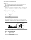
1.12.1.3 Infrared Connector
Serial port 2 can be configured to support an IrDA module with a 5 pin header connector. Once
configured for IrDA, the user can transfer files to or from portable devices such as laptops, PDAs
and printers using application software such as LapLink. The IrDA specification provides for data
transfers at 115 Kbps from a distance of 1 meter. Consumer IR is also supported by the same
connector.
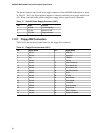
1.12.1.4 Hard Drive LED
This 3-pin, keyed header can be connected to a front panel LED to indicate when hard drive
activity is taking place. When the hard drive is being accessed, the HDACTIVE pin (J2A1-15)
goes low.
1.12.1.5 Power-ON LED
This 2-pin header can be connected to a front panel LED to indicate when power is applied to the
motherboard. When the motherboard is powered up, power is applied to the PWRDRV pin
(J2A1-20) to light the front panel LED.