BX400ii Interposer Board User’s Manual 11
Hardware Reference
3.0 Hardware Reference
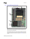
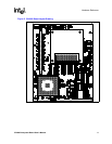
For a hardware layout of the BX400ii Interposer Board, refer to Figure5onpage13. For board
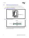
dimensions and keepout space requirements, refer to Figure 2 and Figure3onpage8.
3.1 Connector Definitions
Changes to the hardware are not required for the BX400ii Interposer Board. If necessary, you can
refer to the Mobile Pentium
®
II Processor at 233 MHz, 266 MHz and 300 MHz datasheet (order
number 243669), Intel® Pentium® II Processor Mobile Module: Mobile Module Connector 2
(MMC-2) datasheet (order number 243668) for connector definitions.
3.2 Jumper Settings
Changes to the jumper settings are not required for normal operation of the BX400ii Interposer
Board.
3.2.1 Voltage Regulator Settings
The voltage setting for the V
CC
core is determined by the VID pins, which are signal outputs of the
Mobile Pentium II processor. Jumper settings are available to vary the V
CC
core voltage, however,
these should only be used for validation/debug purposes. For reference purposes, the jumper
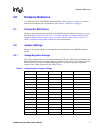
settings for the voltage regulator are provided in Table 3.
Table 3. Voltage Regulator Jumper Settings
JP1 JP2 JP3 JP4 +VCC_CPU
NS NS NS NS 1.25 V
NS NS NS 1-2 1.30 V
NS NS 1-2 NS 1.35 V
NS NS 1-2 1-2 1.40 V
NS 1-2 NS NS 1.45 V
NS 1-2 NS 1-2 1.50 V
NS 1-2 1-2 NS 1.55 V
NS 1-2 1-2 1-2 1.60 V
1-2NSNSNS 1.65V
1-2 NS NS 1-2 1.70 V
1-2 NS 1-2 NS 1.75 V
1-2 NS 1-2 1-2 1.80 V
1-2 1-2 NS NS 1.85 V
1-2 1-2 NS 1-2 1.90 V
1-2 1-2 1-2 NS 1.95 V
1-2 1-2 1-2 1-2 2.00 V
NOTE: 1-2 = Populate Jumper, NS = No Shunt.


