


2727
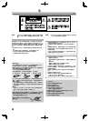
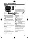
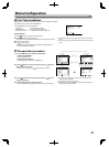
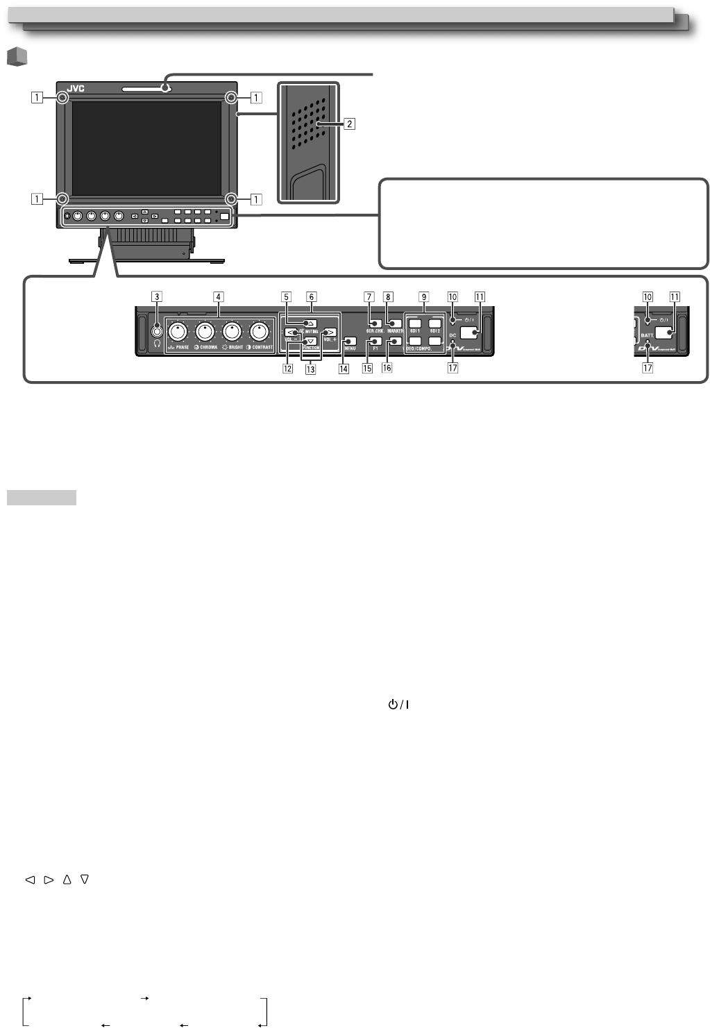
Front panel
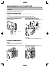
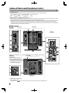
Index of Parts and Functions
“No Effect” is displayed when you press a button which is not •
available for the current input or signal format (the lamp lights
even when the function does not actually work).
The items controlled by the MAKE system cannot be controlled •
by the buttons on the front panel (“Remote On” is displayed
and the lamps do not light).
Tally lamp
This lamp is controlled by the tally function of the MAKE/TRIGGER
terminal.
You can select the color of the tally lamp from “Green” or “Red.” •
You can also select whether the whole lamp is turned on at once,
or whether it is turned on one half at a time. (☞ “Tally Setting” on
page 37 and “External Control” on page 42)
HDMISCOPE
INPUT
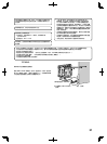
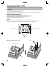
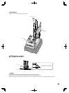
1 Screw holes for attaching protective filter (provided)
Attach the protective filter by using the provided screws.
● Attach the filter to the LCD panel with the frosted side of the
filter facing outwards (when the monitor is shipped from the
factory, protective films are attached to both sides, and a sticker
is attached to the frosted side. Remove the protective films
before use).
CAUTION
● Use only the provided screws to avoid damaging the monitor.
● When attaching the protective filter, do not fasten screws too
tightly; otherwise, the protective filter may be damaged.
2 Speaker (monaural) (DT-V9L5 only)
Outputs the mixed audio of the AUDIO OUT1 terminal and AUDIO
OUT2 terminal. (☞ 9 on page 29)
3 Headphones jack (stereo)
Outputs the same audio signal as that output from the
AUDIO(MONITOR OUT) terminals.(☞ 9 on page 29)
4 Picture adjustment knob
PHASE: Adjusts the picture hue.
CHROMA: Adjusts the picture color density.
BRIGHT: Adjusts the picture brightness.
CONTRAST: Adjusts the picture contrast.
● PHASE and CHROMA cannot be adjusted for certain signal
formats.
● When “Component Phase” is set to “Disable” and an NTSC signal
is input, PHASE can be adjusted. (☞ page 38)
5 MUTING button
Turns off the sound of the speaker(DT-V9L5 only) and of the
headphone. (muting)
●
To cancel the function, press the button again.
● Muting function is also canceled when the volume is adjusted.
(☞ page 30)
● Muting function cannot be activated when a menu screen is
displayed.
6 / / / buttons
When a menu screen is displayed
selects or adjusts menu items.
(☞ “The operation procedure” on page 31)
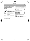
7 SCR. CHK. (Screens check) button/lamp
Displays only the selected element (R, G, B, or the luminance) of
video signal.
● Each time you press this button, the screen changes in the
following order.
Normal screen
Red screenGreen screenBlue screen
Monochrome screen
8 MARKER button/lamp
Displays/hides the area marker and the safety marker.
● Select the size and the style of the markers in “Marker” of the
Main Menu (☞ page 34).
● The marker is not displayed when it is set to “Off” in “Marker”.
(☞ page 34)
9 INPUT SELECT buttons/lamps
Selects an input.
SDI 1: E. AUDIO HD/SD SDI (IN 1) terminal
SDI 2: E. AUDIO HD/SD SDI (IN 2) terminal
VIDEO/COMPO.
: VIDEO/COMPONENT terminal
HDMI: HDMI terminal
● The lamp for the selected input lights.
p Power lamp
The lamp lights as described below.
Unlit: The monitor is completely off (the power switch
on the rear panel is turned off).
In Low Power Mode (☞ page 41)
Lights in green:
The monitor is on.
Lights in orange:
The monitor is off (on standby).
Flashes in orange:
The monitor is in the Power Save (power save) mode.
(
☞
“No Sync Action” in “Sync Function” on page 36)
q button
Turns on and off (on standby) the monitor.
● The power switch is equipped on the rear panel of the monitor.
(☞ 1 on page 28 and 3 on page 29)
w FUNCTION button
Assign functions to the F1 button when the menu is not displayed.
(☞
page 37)
e VOLUME adjustment button/EMBEDDED AUDIO setting
button
Adjusts the volume when no menu screen is displayed.
Selects an audio channel when EMBEDDED AUDIO signals are
contained in SDI input. (☞ “Volume Adjustment/Audio Channel
Selection” on page 30)
r MENU button
Activates/deactivates the display of the Main Menu. (☞ “The
operation procedure” on page 31)
t F1 button/lamp
You can use the functions assigned to this button.
The illustration of the
monitor is of DT-V9L5.
M
I
3 - y are common
to DT-V9L5 and
DT-F9L5.
The illustration on
the right is of DT-
V9L5.
u is displayed as
“BATT.” on DT-F9L5.