


12
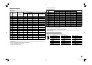
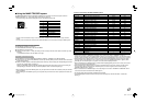
Settings of “E.AUDIO GROUP”
The setting values and selectable audio channels of EMBEDDED AUDIO signals are as follows.
1G: channel(s) 1/2/3/4/1+2/3+4/1 – 4 (1G)
2G: channel(s) 5/6/7/8/5+6/7+8/5 – 8 (2G)
1-2G: channel(s) 1/2/3/4/5/6/7/8/1+2/3+4/5+6/7+8/1 – 4 (1G)/5 – 8 (2G)/1 – 8 (1G+2G)
3G: channel(s) 9/10/11/12/9+10/11+12/9 – 12 (3G)
1-3G: channel(s) 1/2/3/4/5/6/7/8/9/10/11/12/1+2/3+4/5+6/7+8/9+10/11+12/1 – 4 (1G)/5 – 8 (2G)/
9 – 12 (3G)/1 – 8 (1G+2G)/1 – 12 (1-3G)
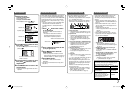
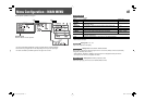
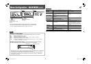
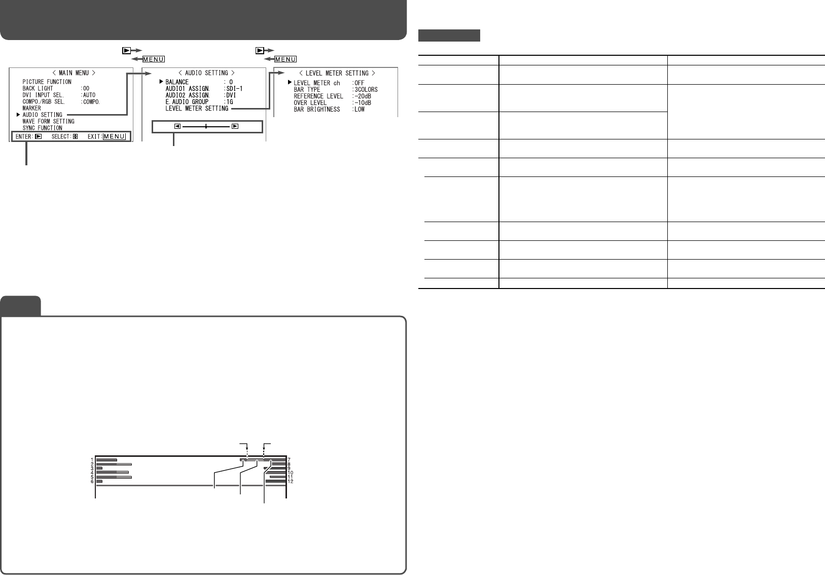
Example of the level meter display —Level meter position and audio channels
Ex.: When “LEVEL METER ch” is set to “LINE” and “BAR TYPE” is set to “3COLORS”
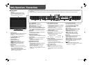
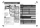
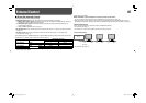
Operation guide
Shows the buttons for each
operation.
• The menu automatically disappears in about 30 seconds after the previous operation.
• Some items may not appear on the menu depending on the input or the input signal.
• The items controlled by the MAKE system do not appear on the menu.
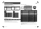
AUDIO SETTING
Settings for the audio output balance, EMBEDDED AUDIO signals and level meter
Item To do Setting value
BALANCE
Adjust the balance between the right and left
speakers.
L5 – L1, 0, R1 – R5
AUDIO1 ASSIGN.
Select the video input which the audio signal
through AUDIO ASSIGN (IN 1) terminal is
assigned to.
SDI-1, SDI-2, DVI, COMP/RGB, VIDEO-1,
VIDEO-2
AUDIO2 ASSIGN.
Select the video input which the audio signal
through AUDIO ASSIGN (IN 2) terminal is
assigned to.
E.AUDIO GROUP*
1
Select the audio channel group of the
EMBEDDED AUDIO signals.
☞ “NOTE”
LEVEL METER
SETTING*
1
Adjust the level meter display for the
EMBEDDED AUDIO signals.
☞ “NOTE”
LEVEL METER ch
Select how the audio channels are displayed on
the level meter.
OFF, LINE (Displays the channels 1 – 6
at the left of the screen and 7 – 12 at the
right.), DIVIDE (Displays the odd channels at
the left of the screen and the even channels
at the right.)
BAR TYPE
Select the color of the level meter display. 3COLORS (3 colors to indicate variations in
input levels), W.100 (white)
REFERENCE
LEVEL
Select the standard input level indicated on the
level meter.
–20dB, –18dB
OVER LEVEL
Select the input level’s lower limit indicated in
red for the “3COLORS” display.
–10dB, –8dB, –6dB, –4dB, –2dB
BAR BRIGHTNESS
Select the brightness of the level meter. LOW, HIGH
*
1
Memorized for each input.
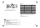
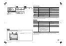
OVER LEVEL REFERENCE LEVEL
Yellow
Green
Red
Adjustment bar
Displayed when selecting
“BALANCE.”
NOTE
• When “BAR TYPE” is set to “W.100,” the standard input level set in “REFERENCE LEVEL” is displayed with
the line indication. The input level set in “OVER LEVEL” is not displayed.
• The level meter with no audio signal input is displayed in white for “3COLORS,” and in gray for “W.100.”
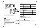
• You can select the position of the level meter display—top or bottom of the screen (☞ “POSITION” in
“INFORMATION” on page 15).
Menu Configuration—MAIN MENU
(cont.)
DT-V24_20L3D_EN.indd 12DT-V24_20L3D_EN.indd 12 08.5.27 5:15:04 PM08.5.27 5:15:04 PM