


17
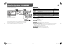
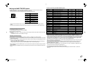
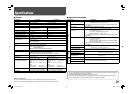
7 Using the MAKE/TRIGGER system
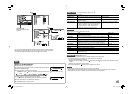
The MAKE/TRIGGER terminal is configured as follows. You can assign a function to each pin terminal in
“REMOTE SETTING” (☞ “PIN1, PIN2, PIN3, PIN4, PIN5” on page 15).
• You cannot change the functions assigned to the pin terminals from 6th to 8th.
Pin No.
Pin name
1
PIN1
2
PIN2
3
PIN3
4
PIN4
5
PIN5
6
PIN6 (TALLY)*
1
7
PIN7 (ENABLE)*
2
8
PIN8 (GND)
*
1
The 6th pin terminal controls turning on or off the tally lamp (available to control even when the 7th pin terminal is
invalid).
*
2
The 7th pin terminal makes the external control valid/invalid. Make sure to control the terminal by the MAKE system.
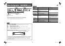
To assign the functions to the pin terminals
For the operation procedure, see page 7.
1 Select “REMOTE SETTING” on the SET-UP MENU.
2 Set “PARALLEL TYPE” to “SET.”
3 Select a pin name (“PIN1” – “PIN5”) for which you want to assign a function, then select the function you want
to assign.
• For selectable functions, see the tables on the right.
Operation of the external control
1 Set “PARALLEL TYPE” of “REMOTE SETTING” to “MAKE” or “TRIGGER” in the SET-UP MENU.
2 Short-circuit the 7th pin terminal (ENABLE) to the 8th pin terminal (GND) so that the monitor can be controlled
by the external control.
3 When the “MAKE” system is selected: Operate each function by short-circuiting the corresponding pin terminal
to the 8th pin terminal (GND) or opening it.
When the “TRIGGER” system is selected: Operate each function by pulse control, that is short-circuiting the
corresponding pin terminal to the 8th pin terminal (GND) for about 1 second and opening it.
• When changing the input with MAKE system, only one pin terminal must be short-circuited. (Other pin terminals
must be opened.)
• When selecting the “TRIGGER” system, you can operate only one function at a time. Operate the functions one
by one.
This is a female terminal.
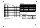
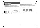
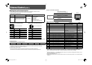
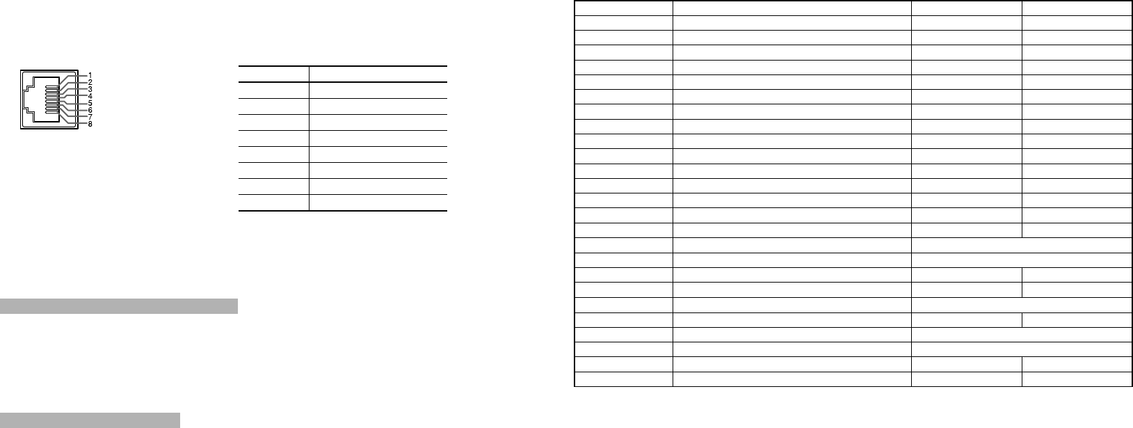
<Functions controlled by the MAKE/TRIGGER system>
Display Functions to be controlled Opening Short-circuiting
TALLY SEL Selects the color of the tally lamp. Green Red
SDI 1 Changes the input to “SDI 1.” Invalid Valid
SDI 2 Changes the input to “SDI 2.” Invalid Valid
DVI Changes the input to “DVI.” Invalid Valid
COMP./RGB Changes the input to “COMPO./RGB.” Invalid Valid
VIDEO 1 Changes the input to “VIDEO 1.” Invalid Valid
VIDEO 2 Changes the input to “VIDEO 2.” Invalid Valid
EXT.SYNC Changes the sync signal. Internal sync External sync
A.MARKER The area marker indication Off On
S.MARKER The safety marker indication Off On
FRAME Indication of the area of
the specified aspect ratio
Off On
C.MARKER The center marker indication Off On
MARK.SEL Selects the items of “MARKER”*
3
Non-“R-” items “R-” items
ASPECT Changes the aspect ratio. 4:3 16:9
1:1 Displays in 1:1 mode. Off On
STATUS Status display*
4
☞ “On the Status Display” on page 7
L.METER Audio level meter display *
5
TIME CODE Time code display Off On
SOURCE ID
☞ “SOURCE ID” on page 15
Off On
WAVE FORM Wave form monitor display *
6
COLOR OFF Color off Color Monochrome
SCR CHECK Screens check *
7
I/P MODE Change a mode according to a input picture. *
8
MUTING Muting on/off Off On
– – – No function — —
*
3
Selects which functions in “MARKER” are activated, non-“R-” items or “R-” items (☞ “MARKER” on page 11).
*
4
Displays the information shown when INPUT SELECT button of the current input is pressed (☞ “On the Status Display”
on page 7). While controlling with the MAKE system, the information is displayed only at the moment of short-circuiting.
*
5
While controlling with the MAKE system, the level meter is switched between displayed (short-circuiting) and hidden
(opening). When “LEVEL METER ch” is set to “OFF,” the level meter is not displayed (“NO EFFECT” appears). While
controlling with the TRIGGER system, the pattern of the audio channel display is switched.
*
6
Must be controlled with the TRIGGER system. Controls whether displaying/hiding the wave form monitor (This function
cannot be controlled with the MAKE system.).
*
7
While controlling with the MAKE system, the screen is switched between normal screen (opening) and blue screen
(short-circuiting). While controlling with the TRIGGER system, the screen changes as same as when pressing
SCREENS CHECK button (☞ page 6).
*
8
Must be controlled with the TRIGGER system. The mode changes in the order of “NORMAL”
\
“CINEMA”
\
“FIELD”.
(This function cannot be controlled with the MAKE system.)
• You cannot assign the same function to different pin terminals.
• The TRIGGER system switches each function by short-circuiting the pin terminal for about 1 second and
opening it.
DT-V24_20L3D_EN.indd 17DT-V24_20L3D_EN.indd 17 08.5.27 5:15:12 PM08.5.27 5:15:12 PM