


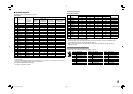
8
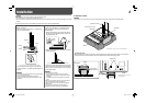
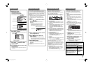
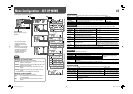
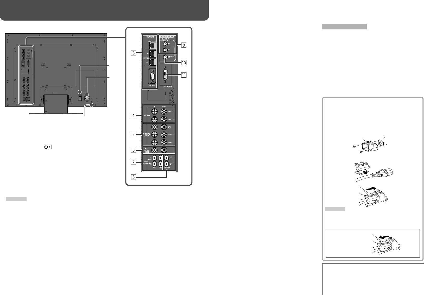
7 Rear panel
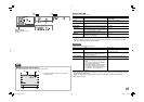
Daily Operations / Connections (cont.)
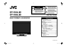
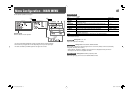
The illustration of the monitor is of DT-V24L3D.
1 Power switch
Tur ns the power on or off.
• You need to press button (☞ u on page
6) to use the monitor after turning on the power
switch.
2 AC IN terminal
AC power input connector.
Connect the provided AC power cord to an AC
outlet.
• Attach the provided power cord holder to prevent
accidental disconnection of the AC power cord (☞
on the right).
CAUTION
Do not connect the power cord until all other
connections are completed.
3 REMOTE terminal
Ter minal for controlling the monitor by an external
control. (☞ “External Control” on page 16)
4 VIDEO (INPUT 1/INPUT 2) terminals (BNC)
Input (IN) and output (OUT) terminals for the
composite signals.
5 COMPO./RGB (G/Y, B/PB/B-Y, R/PR/R-Y) terminals
(BNC)
Input (IN) and output (OUT) terminals for the
analog component (color difference) or analog RGB
signals.
• Select the signal type in “COMPO./RGB SEL.”
corresponding to the type of the input signal (☞
page 10).
8
Note for connections
• Before making any connections, turn off all the
equipment.
• Use a cord whose plugs correctly match the
terminals on this monitor and the equipment.
• Plugs should be firmly inserted; poor connections
could cause noise.
• When unplugging a cord, be sure to grasp its plug
and pull it out.
• DO NOT connect the power cord until all connections
are complete.
• Refer also to the user manual of each piece of
equipment.
Security slot
Attach a security wire to this slot.
6 EXT.SYNC (CS) terminals (BNC)
Input (IN) and output (OUT) terminals for the
external composite sync (Cs) signals.
• To use these terminals, set “SYNC INPUT SEL.”
to “EXT.” (☞ “SYNC FUNCTION” on page 13)
• The terminals are for all VIDEO (INPUT 1, INPUT
2) and COMPO./RGB.
• When an external sync signal is input, external
synchronization has priority over all VIDEO 1,
VIDEO 2 and COMPO./RGB input.
7 AUDIO ASSIGN (IN 1/IN 2) terminals (pin jack)
Input terminals for the analog audio signals.
• Use this terminal for the analog audio connection
of the SDI.
• Select the video input to assign the audio signal
in “AUDIO1 ASSIGN.” or “AUDIO2 ASSIGN.” (☞
“AUDIO SETTING” on page 12).
8 AUDIO ASSIGN (MONITOR OUT) terminals
(pin jack)
Output terminals for the analog audio signal.
• The terminals output the audio signal through
AUDIO ASSIGN (IN 1 or IN 2) terminals when
you select the video input you have selected for
“AUDIO1 ASSIGN.” or “AUDIO2 ASSIGN.” in
“AUDIO SETTING” (☞ page 12).
• The signal is output from this terminal only when
the monitor is on or in “P.SAVE” (power save)
mode. (☞ “NO SYNC ACTION” on page 13)
• The EMBEDDED AUDIO signal...
– is decoded into an analog signal, then emitted.
– is emitted only when “SDI 1” or “SDI 2” is
selected, and when EMBEDDED AUDIO
signals come in to the E. AUDIO HD/SD SDI
(IN 1 or IN 2) terminal.
– has priority over the audio signal input to
AUDIO ASSIGN (IN 1 or IN 2) terminals when
“SDI-1” or “SDI-2” is selected for “AUDIO1
ASSIGN.” or “AUDIO2 ASSIGN.” and the
EMBEDDED AUDIO signal is input to E.AUDIO
HD/SD SDI (IN 1 or IN 2) terminal.
9 E. AUDIO HD/SD SDI (IN 1, IN 2) terminals (BNC)
Input terminals for the HD/SD SDI signals.
• The terminals accept also EMBEDDED AUDIO
signals including up to 12 audio channels with a
sampling frequency of 48 kHz.
p E. AUDIO HD/SD SDI (SWITCHED OUT) terminal
(BNC)
Output terminal for the HD/SD SDI signals.
• The SDI signals of the current input (SDI 1 or SDI
2) are re-clocked, then emitted.
• When an input other than SDI 1 and SDI 2 is
selected, the SDI signal of the input selected last
time is emitted from this terminal.
• The signals are emitted from this terminal only
when the monitor is on or in “P.SAVE” (power
save) mode.
q DVI-D (HDCP) terminal
Input terminal for the DVI-D signal compatible with
HDCP.
• When the picture is not displayed correctly,
change the setting of “DVI INPUT SEL.”
(☞ page 10).
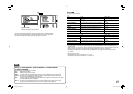
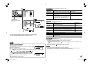
Using the audio level meter
You can check the conditions of the current
EMBEDDED AUDIO signals in the audio level meter.
(☞ “
On the Information Display
” on page 7)
Make the setting for the level meter in
“LEVEL METER
SETTING” (
☞
“AUDIO SETTING” on page 12).
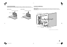
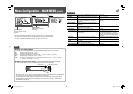
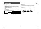
Attaching the power cord holder
The provided power cord holder prevents accidental
disconnection of the AC power cord from the AC IN
terminal.
• The power cord holder consists of two parts, a
case and a cover.
1
2
3
CAUTION
• Use only the provided screws.
• Make sure the plug will not be pulled out after the
cover is attached to the case.
To detach the cover
AC IN terminal
Case
Cover
2
1
DT-V24_20L3D_EN.indd 8DT-V24_20L3D_EN.indd 8 08.5.27 5:14:58 PM08.5.27 5:14:58 PM