J
V
C
0600HISFLEJES
EN, GE, FR
1
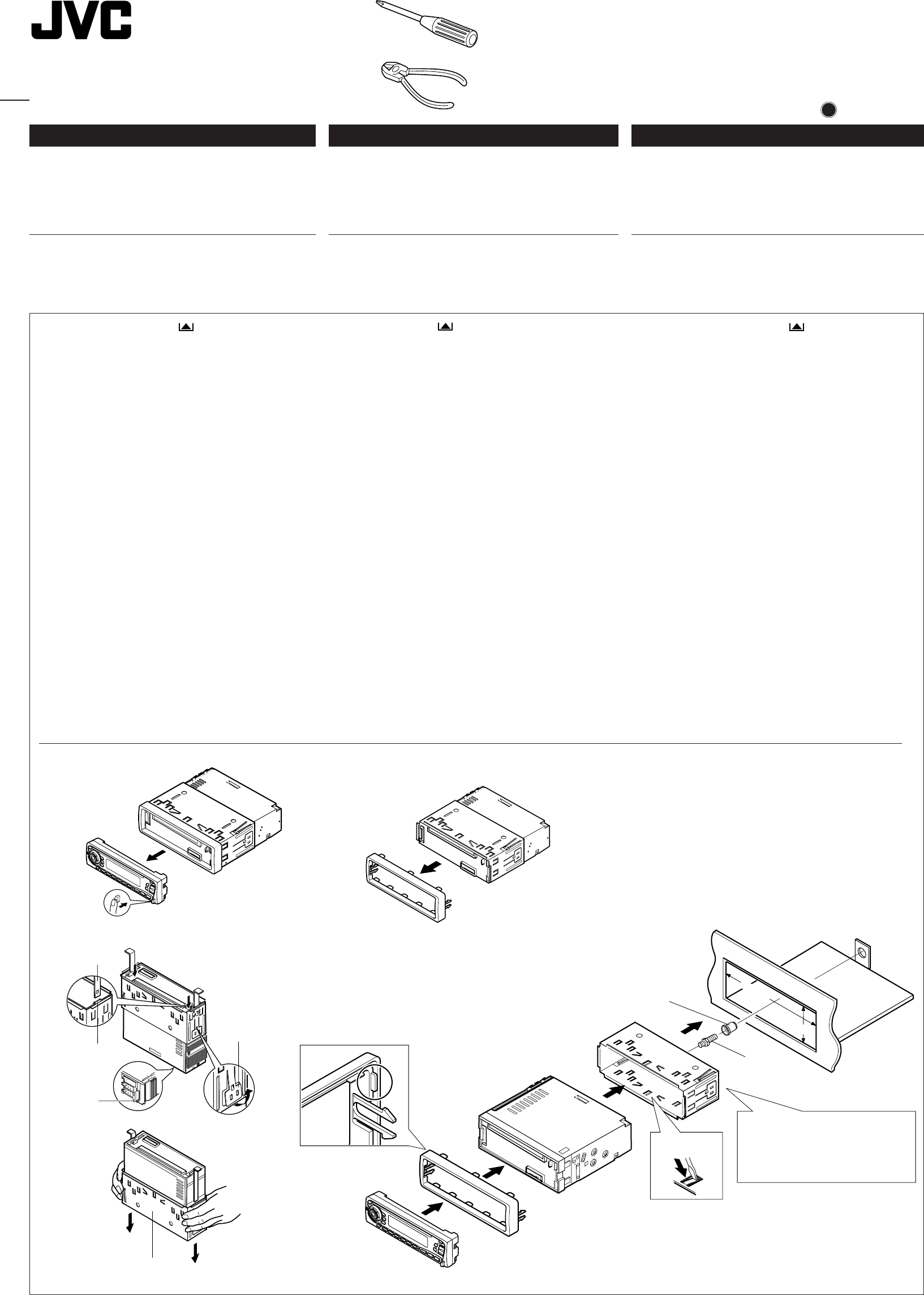
Before mounting: Press (Control Panel Release
button) to detach the control panel.
2
Remove the trim plate.
3
Remove the sleeve after disengaging the sleeve locks.
1 Stand the unit.
Note: When you stand the unit, be careful not to damage
the fuse on the rear.
2 Insert the 2 handles between the unit and the sleeve, as
illustrated, to disengage the sleeve locks.
3 Remove the sleeve.
Note: Be sure to keep the handles for future use after
installing the unit.
4
Install the sleeve into the dashboard.
* After the sleeve is correctly installed into the dashboard,
bend the appropriate tabs to hold the sleeve firmly in place,
as illustrated.
5
Fix the mounting bolt to the rear of the unit’s body and place
the rubber cushion over the end of the bolt.
6
Do the required electrical connections.
7
Slide the unit into the sleeve until it is locked.
8
Attach the trim plate so that the projection on the trim plate
is fixed to the left side of the unit.
9
Attach the control panel.
1
Vor dem Einbau: (Schalttafel-Freigabetaste) zum
Lösen der Schalttafel drücken.
2
Den Frontrahmen herausnehmen.
3
Die Halterung nach dem Entriegeln der Halterungensperren
abnehmen.
1 Das Gerät aufstellen.
Hinweis: Beim Aufstellen des Geräts darauf achten,
daß die Sicherung auf der Rückseite nicht beschädigt
wird.
2 Die beiden Griffe zwischen dem Gerät und der
Halterung wie abgebildet einstecken und die
Halterungensperren entriegeln.
3 Die Halterung entfernen.
Hinweis: Sicherstellen, daß die Griffe für künftigen
Gebrauch nach dem Einbau des Geräts aufbewahrt
werden.
4
Die Halterung im Armaturenbrett einbauen.
* Nach dem korrekten Einbau der Halterung im
Armaturenbrett, die entsprechenden Riegel umknicken,
um die Halterung an ihrem Platz zu sichern, siehe
Abbildung.
5
Die Befestigungsschraube an der Rückseite des
Gerätekörpers befestigen und das Ende der Schraube mit
einem Gummipuffer abdecken.
6
Nehmen Sie die erforderlichen elektrischen Anschlüsse vor.
7
Das Gerät in die Halterung schieben, bis es einrastet.
8
Befestigen Sie die Frontrahmen in der Form, daß der
Fortsatz der Frontrahmen auf der linken Seite des Geräts
befestigt wird.
9
Die Schalttafel anbringen.
1
Avant le montage:
Appuyer sur (touche de libération
du panneau de commande) pour détacher le panneau de
commande.
2 Retirer la plaque d’assemblage.
3 Libérer les verrous du manchon et retirer le manchon.
1
Poser l’appareil à la verticale.
Remarque:
Lorsque vous mettez l’appareil à la verticale,
faire attention de ne pas endommager le fusible situé
sur le fond.
2
Insérer les 2 poignées entre l’appareil et le manchon
comme indiqué pour désengagé les verrous de manchon.
3
Retirer le manchon.
Remarque:
S'assurer de garder les poignées pour une
utilisation ultérieur, après l'installation de l'appareil.
4 Installer le manchon dans le tableau de bord.
* Après installation correcte du manchon dans le tableau
de bord, plier les bonnes pattes pour maintenir fermement
le manchon en place, comme montré.
5 Monter le boulon de montage sur l’arrière du corps de
l’appareil puis passer l’amortisseur en caoutchouc sur
l’extrémité du boulon.
6 Réalisez les connexions électriques.
7 Faire glisser l’appareil dans le manchon jusqu’à ce qu’il soit
verrouillé.
8 Attachez la plaque d’assemblage de façon que la projection
de la plaque soit fixée sur le côté gauche de l’appareil.
9 Remonter le panneau de commande.
FRANÇAIS
•
Cet appareil est conçu pour fonctionner sur des sources de
courant continu de 12 volts à masse NEGATIVE.
INSTALLATION
(MONTAGE DANS LE TABLEAU DE BORD)
•
L’illustration suivante est un exemple d’installation typique.
Cependant, vous devez faire les ajustements correspondant à
votre voiture particulière. Si vous avez des questions ou avez
besoin d’information sur des kits d’installation, consulter votre
revendeur d’autoradios JVC ou une compagnie
d’approvisionnement.
DEUTSCH
• Dieses Gerät ist für einen Betrieb in elektrischen Anlagen mit
12 V Gleichstrom und (–) Erdung ausgelegt.
EINBAU
(IM ARMATURENBRETT)
• Die folgende Abbildung zeigt einen typischen Einbau. Dennoch
müssen Sie entsprechend Ihrem jeweiligen Auto Anpassungen
vornehmen. Bei irgendwelchen Fragen oder wenn Sie
Informationen hinsichtlich des Einbausatzes brauchen, wenden
Sie sich an ihren JVC Autoradiohändler oder ein Unternehmen
das diese Einbausätze vertreibt.
ENGLISH
• This unit is designed to operate on 12 volts DC, NEGATIVE
ground electrical systems.
INSTALLATION
(IN-DASH MOUNTING)
• The following illustration shows a typical installation. However,
you should make adjustments corresponding to your specific
car. If you have any questions or require information regarding
installation kits, consult your JVC IN-CAR ENTERTAINMENT
dealer or a company supplying kits.
Fuse
Sicherung
Fusible
1
Sleeve
Halterung
Manchon
Lock plate
Arretierplättchen
Plaque de verrouillage
Slot
Schlitz
Fente
Handle
Griffe
Poignée
3
184 mm
53 mm
Trim plate
Frontrahmen
Plaque d’assemblage
8
9
7
Sleeve
Halterung
Manchon
Rubber cushion
Gummipuffer
Amortisseur en caoutchouc
4
5
Dashboard
Armaturenbrett
Tableau de bord
4
*
6
2
Mounting bolt
Befestigungsschraube
Boulon de montage
See “ELECTRICAL CONNECTIONS.”
Siehe „ELEKTRISCHE ANSCHLÜSSE“.
Référez-vous “RACCORDEMENTS
ELECTRIQUES.”
KD-SX878R
KD-S777R/KD-S8R
Installation/Connection Manual
Einbau/Anschlußanleitung
Manuel d’installation/raccordement
FSUN3117-T212
[E]
Instal.SX878R/S777R.EN/GE/FR 08/09/2000, 03:55 PM1


