


E-8
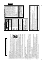
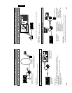
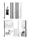
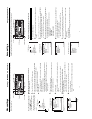
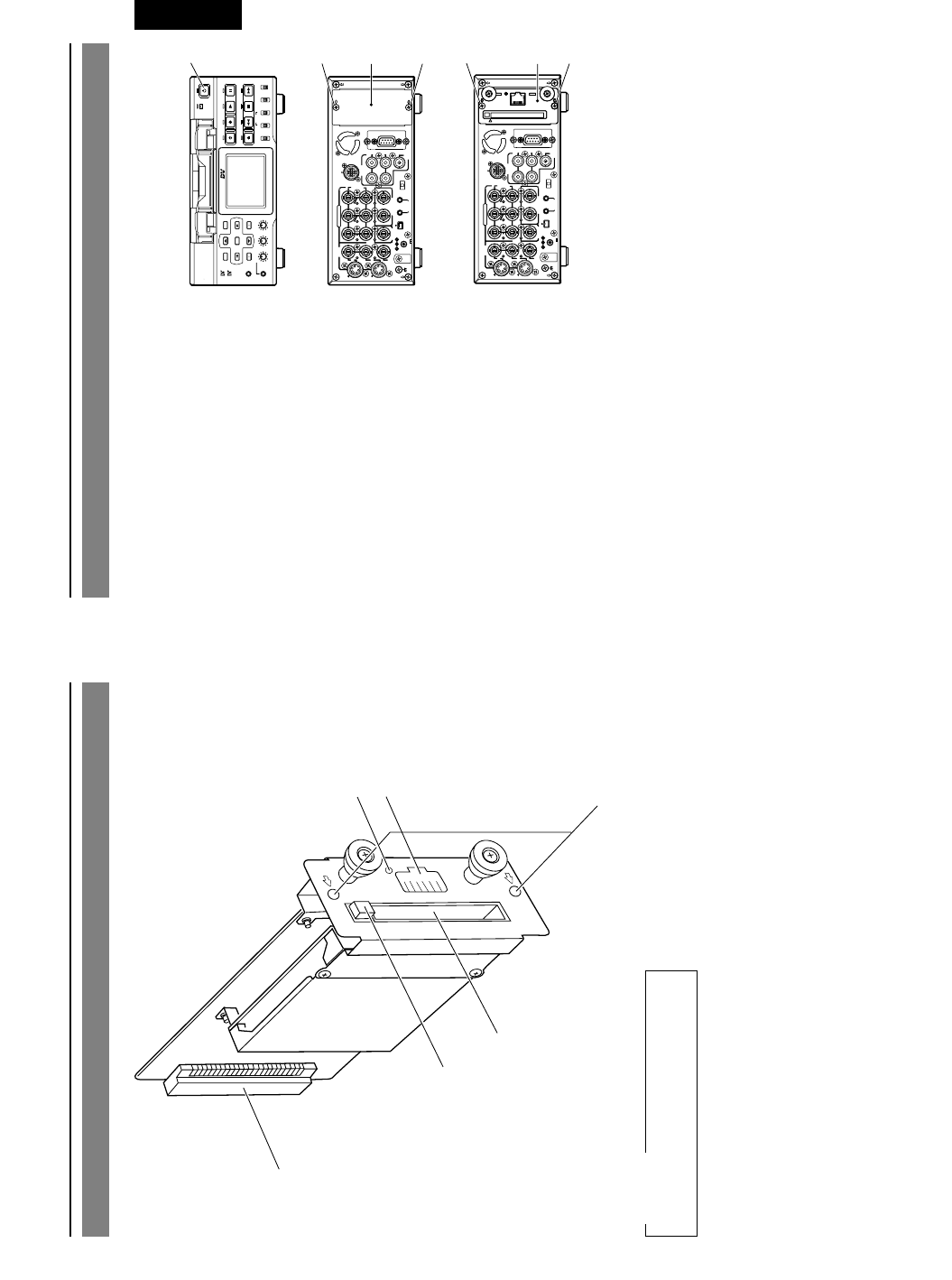
1 PC Card Slot
Insert LAN card, CompactFlash card, etc.
here.
2 EJECT Button
Push to eject the card.
3 Mounting screw holes
Used to install this product to the rear
panel of the BR-DV6000 with screws.
Names and Functions of Parts
5
3
1
2
4
6
4 Connector
Connects by pushing in the connector for
connecting to the VCR main unit.
5 LAN Connector
Connect LAN cable here.
6 LINK LED
Lights up when network is connected.
Please don’t touch the metal parts other
than the panel.
CAUTION
E-9
English
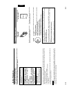
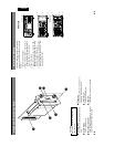
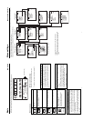
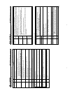
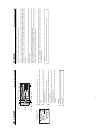
Installation Method
Follow the following procedure to install this
product to the BR-DV6000 DV Video Cassette
Recorder.
1 Switch off the VCR power.
2 Remove the two screws 2 from the cover
of the optional board installation slot on
the far right side of the rear panel.
3 Remove the cover 3.
4 Insert the board of this product (SA-
DV6000) along the guide rails, correctly
align the connectors and push in.
5 Fix the SA-DV6000 onto the BR-DV6000
main unit using the two screws 2 that
were removed in step 2.
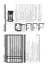
BR-DV6000
PROFESSIONAL
MENU RESET
A.DUB
EJECT
COUNTER
AUDIO INPUT
SELECT
MONITOR OUTPUT REMOTE
LOCAL
CTL L
MIX
R
CH-1/2
MIX
CH-3/4
DV
LINE
Y/C
(CPN)
TC
UB
REW STOP FF
REC
OPERATE
PLAY PAUSE
DISP
SET SEARCH+
BLANK CUE UP
HOLD
PHONES REC LEVEL
CH-1/3 CH-2/4
MIC
SEARCH–
Mini
VIDEO
LINE
IN
OUT
MONITOR
OUT
DC12V
DV
IN/OUT
IN OUT
OFF
AUDIO
REMOTE2
IN
B-YR-Y
SYNC IN
TIME CODE
IN OUT
Y
COMPONENT
OUT
CH 1/3 CH 2/4
IN
OUT
MONITOR
OUT
REMOTE1
TIMER
REC PLAY
SERIAL
REMOTE
SIGNAL
GND
Y/C
VIDEO
LINE
IN
OUT
MONITOR
OUT
DC12V
DV
IN/OUT
IN OUT
OFF
AUDIO
REMOTE2
IN
B-YR-Y
SYNC IN
TIME CODE
IN OUT
Y
COMPONENT
OUT
CH 1/3 CH 2/4
IN
OUT
MONITOR
OUT
REMOTE1
TIMER
REC PLAY
SERIAL
REMOTE
SIGNAL
GND
Y/C
LAN
2
3
5
5
4
1
2
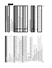
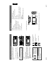
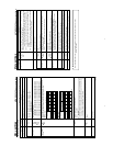
BR-DV6000
Front Panel
Rear Panel