


KRK-11
HANDHELD CONTROL HEAD INTERFACE KIT
INSTRUCTION MANUAL
© B62-2102-00 (M)
Features
・
This is an optional accessory for the KCH-16.
・
You can connect an external speaker to the interface box.
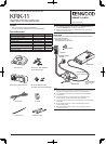
supplied accessories
Item Part Number Quantity
Interface Box
−
1
Main body panel assembly
−
1
Ground cable E30-3085-XX 1
Retaining band J61-0307-XX 1
Retaining bracket J21-4354-XX 2
Connector E59-0426-XX 1
Screw set N99-2069-XX 1
Screw set N99-2070-XX 1
Instruction manual B62-2102-XX 1
Main body panel assembly
Screw set : N99-2069-XX
(For Interface box)
Interface box
Ground cable
Retaining band Retaining bracket
Screw set N99-2070-XX
(For Main body panel assembly)
Connector
Note:
◆
The following instructions are for use by your
Kenwood
dealer, an
authorized
Kenwood
service facility, or the factory.
◆
Refer to the Service manual for detailed information regarding the
installation of the KCH-16.
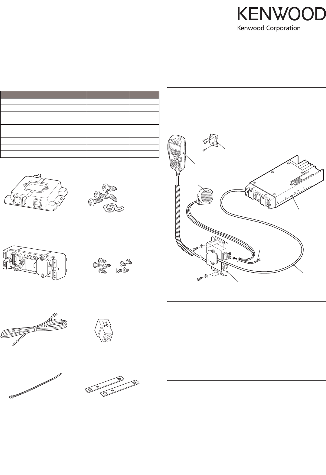
installation
The following tools and parts are required for installing the handheld
control head interface kit.
・
Phillips No. 2 screw driver
・
KCT-22 Remote Control Cable
Transceiver
External speaker
(Option)
KCT-22 (Option)
Remote Control
Cable
Interface box
KCH-16
hanger
Note:
◆
When connecting the KCH-16 to the Interface box, do not connect
the MIC to the programming connector of the Interface box.
◆
The programming connector of the interface box is dedicated to
programming.
◆
The control connector of the interface box is dedicated to the
KCH-16; do not use this connector for other equipment.
◆
The optional jack is supplied for future expansion. It cannot be used
at this time.
◆
Do not remove the covers or caps of connectors that are not
currently being used.
◆
After connecting the KCH-16 and turning on the power, do not
remove the KCH-16.
KCT-18 (Option)
Ignition Sense Cable