


47
Lenovo IdeaPad Z560/Z565
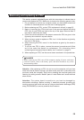
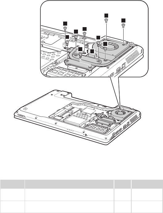
1070 Fan assembly and Heat Sink assembly
For access, remove these FRUs in order:
• “1010 Battery pack” on page 40
• “1030 Hard disk drive (HDD)/Memory/CPU (Central processing unit)/Mini
PCI ExpressCard slot compartment cover ” on page 42
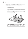
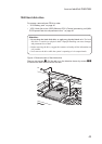
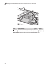
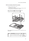
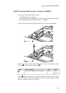
Figure 7. Removal steps of fan assembly and heat sink assembly
Note: Remove ve screws
1
and four spring screws
2
.
Unplug the connector in the direction shown by arrow
3
.
3
2
2
2
1
1
1
1
1
2
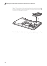
When installing: Make sure that the fan connector is attached rmly to the
system board.
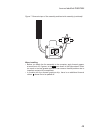
Step Screw (quantity) Color Torque
1
M2.5 × 4 mm, at-head, nylon-coated (5) Black 0.6 Nm
(6 kgfcm)
2
M2.0 × 3.2 mm, with spring, nylon-coated (4) Silver 2.0~2.5 Nm
(2.0~2.5 kgfcm)