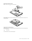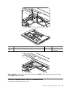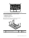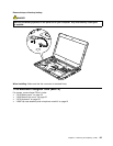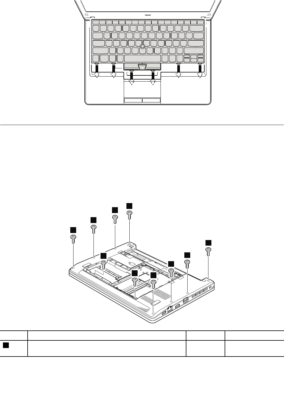
3. Secure the keyboard by tightening the screws from the bottom side of the computer.
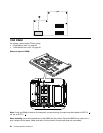
1080 Top case assembly and microphone module
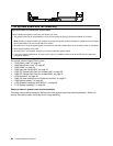
For access, remove these FRUs in order:
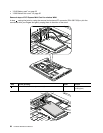
• “1010 Battery pack” on page 52
• “1020 Bottom slot cover” on page 52
• “1040 Hard disk drive (HDD)” on page 55
• “1070 Keyboard” on page 59
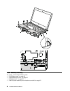
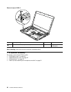
Note: Microphone module is attached on the underside of the top case assembly.
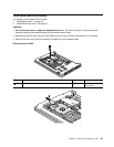
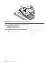
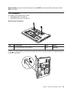
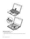
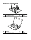
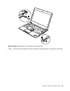
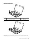
Removal steps of top case assembly and microphone module
1
1
1
1
1
1
1
1
1
1
Step Screw (quantity) Color
Torque
1
M2 × 5 mm, at-head, nylon-coated (10)
Black 0.181 Nm
(1.85 kgfcm)
Chapter 8. Removing and replacing a FRU 61


