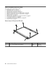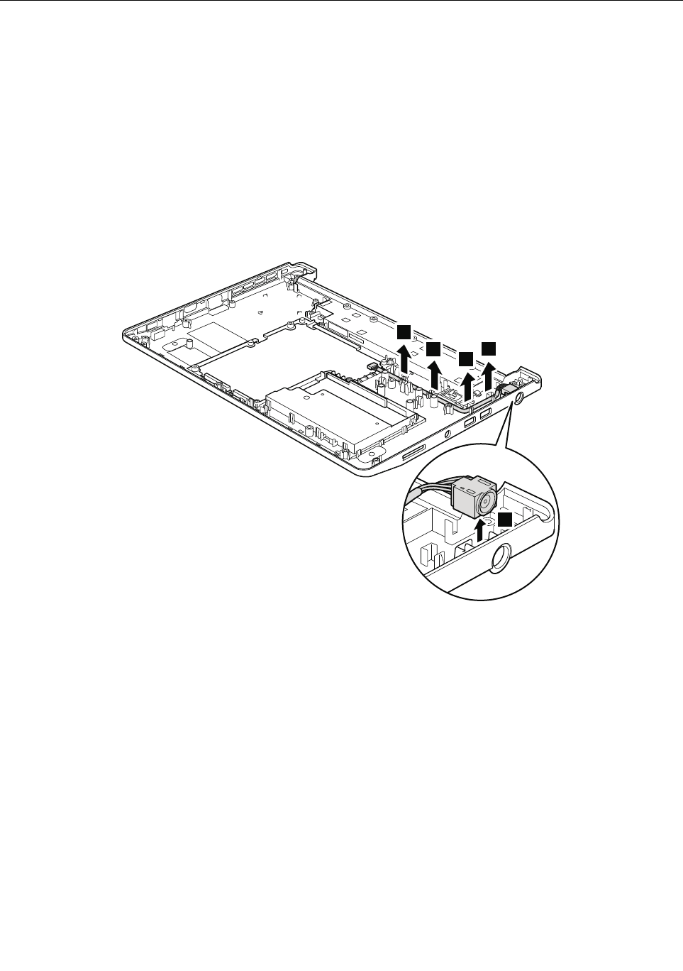
1150 Base cover assembly and DC-in cable
For access, remove these FRUs in order:
• “1010 Battery pack” on page 52
• “1020 Bottom slot cover” on page 52
• “1040 Hard disk drive (HDD)” on page 55
• “1050 PCI Express Mini Card for wireless LAN” on page 56
• “1060 PCI Express Mini Card for wireless WAN” on page 57
• “1070 Keyboard” on page 59
• “1080 Top case assembly and microphone module” on page 61
• “1110 Speaker assembly” on page 66
• “1120 System board and fan assembly” on page 68
• “1140 LCD unit” on page 77
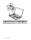
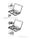
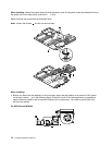
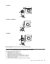
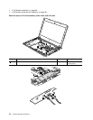
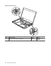
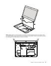
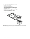
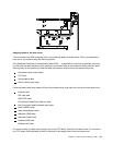
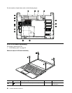
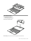
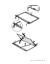
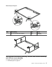
Removal steps of base cover assembly and DC-in cable
1
1
1
1
2
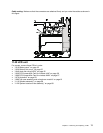
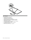
Cable routing: Make sure that the cable is attached to the cable guides as shown in this gure. When you
route the cables, make sure that they are not subjected to any tension. Tension could cause the cables to be
damaged by the cable guides, or a wire to be broken.
80 Hardware Maintenance Manual


