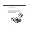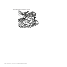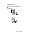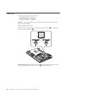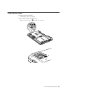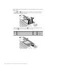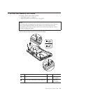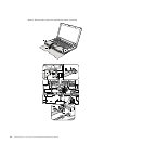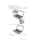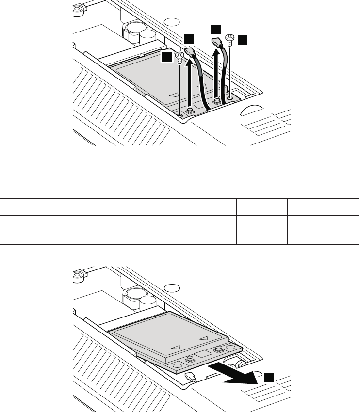
Table 18. Removal steps of wireless WAN slot cover and PCI Express Mini Card for wireless
WAN (continued)
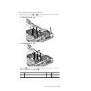
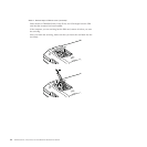
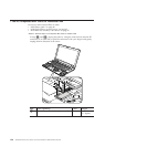
In step 3a and 3b, unplug the jacks by using the removal tool antenna RF
connector (P/N: 08K7159) or pick the connectors with your fingers and gently
unplug them in direction of the arrow.
4
4
3a
3b
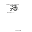
When installing: Plug the red cable 3a into the jack labeled MAIN , and the
blue cable 3b into the jack labeled AUX on the card.
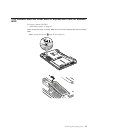
Step Screw (quantity) Color Torque
4 M2 × 3 mm, wafer-head, nylon-coated (2) Black 0.167 Nm
(1.7 kgfcm)
5
96 ThinkPad SL410, L410, SL510, and L510 Hardware Maintenance Manual


