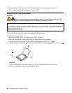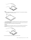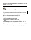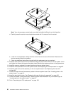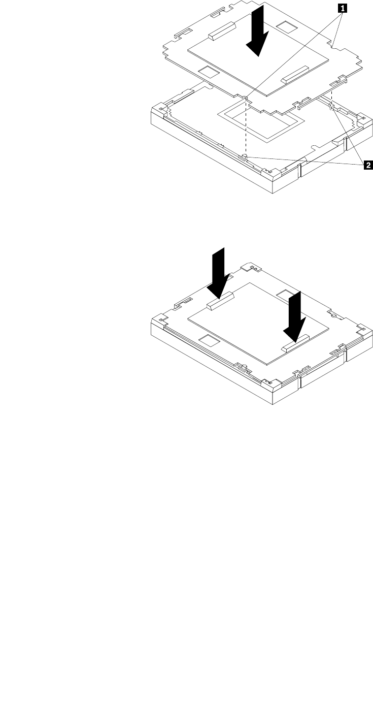
Note: Your microprocessor socket and cover might look slightly different from the illustration.
d. Carefully press the socket cover straight downwards until it is secured into the socket.
e. Lower the microprocessor retainer and then lower the lever to secure the retainer. Make sure the
lever is securely locked into position.
f. Follow any additional instructions included with the replacement part you received.
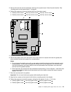
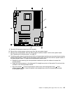
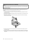
13. Install the new system board into the chassis and align the screw holes with those in the chassis. Insert
and tighten the screws that secure the system board following the sequence shown in the gure above.
14. Install the memory modules in the same location on the new system board.
15. Install the microprocessor on the new system board. See “Replacing the microprocessor” on page 92
16. Install the heat sink and fan assembly on the new system board. See “Replacing the heat sink”
on page 90
.
17. Connect the heat sink and fan assembly cable to the new system board. See “Locating parts on the
system board ” on page 81.
18. Install the hard disk drive fan. See “Replacing the hard disk drive fan assembly” on page 100.
19. Connect all cables to the system board. See the system board illustration for your machine type at
“Locating parts on the system board ” on page 81.
20. Go to “Completing the FRU replacement” on page 108.
96 ThinkStation Hardware Maintenance Manual


