Connectors, LEDs, and jumpers
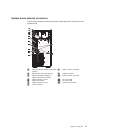
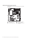
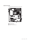
The illustrations in this section show the connectors, light-emitting diodes (LEDs),
and jumpers on the system board. The illustrations might differ slightly from your
hardware.
System board internal connectors
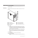
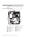
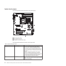
The following illustration shows the internal connectors on the system board.
1 Microprocessor power connector 11 Hot-swap hard disk drive backplanar
connector
2 Main power connector 12 USB tape drive connector
3 Microprocessor fan connector 13 PCI-X enablement card connector
4 (optional) External USB diskette drive
connector
14 Mini-PCI slot
5 DIMM connectors 15 Mini-BMC JTAG connector
6 Microprocessor connector 16 Mini-BMC boot loader
7 Front panel 17 Wake on LAN
8 Hard disk drive fan connector 18 Battery
9 Front USB connectors 19 System fan connector
10 SATA connector
10 ThinkServer TS100 Types 6431, 6432, 6433, and 6434: Hardware Maintenance Manual


